Wear Ring HZB253-640-03-04-00 for Feedwater Booster Pump: Critical Spot Welding Requirements


Booster Pump Wear Ring Replacement: The Critical Importance of Re-Spot Welding
In the routine maintenance of pre-pumps (booster pumps), replacing the wear ring is a standard task. However, the absolutely vital step of "re-spot welding" is frequently overlooked. This negligence is the primary cause of wear ring loosening, uneven wear, leading to devastating drops in pump efficiency, or even catastrophic shutdowns. Today, we will leverage the technical guidelines from China's power industry standard, DL/T 893-2019 (Selection and Usage Guidelines for Power Plant Feedwater Pumps), to detail the critical spot welding techniques for booster pump wear rings, helping you steer clear of common maintenance pitfalls.
Why is Re-Spot Welding Mandatory?
The wear ring is a key sealing element in the pre-pump, creating the working clearance with the impeller (new clearance: 0.70–0.88 mm; maximum allowable: 1.76 mm). Per Section 7.3.4 of the DL/T 893-2019 standard, it is explicitly required: "After wear ring replacement, spot welding must be performed for fixation. Spot weld locations shall be evenly distributed to prevent deformation caused by localized overheating."
If this spot welding step is skipped, the wear ring is highly susceptible to displacement during operation. This results in uneven wear between the impeller and the ring, creating deep grooves. In severe cases, pump efficiency can plummet by over 20%, potentially forcing an emergency equipment shutdown.
Don't risk major failure! Click here to request our detailed guide on adherence to DL/T 893-2019 standards and guarantee your pump's long-term efficiency.
In-Depth Spot Welding Technical Specifications
1. Spot Welding Location
- Standard Requirement: DL/T 893-2019 dictates that spot weld points must be distributed symmetrically around the outer circumference of the wear ring, strictly avoiding the impeller contact area (a 120° angular region is often recommended to be avoided).
- Practical Execution: Select three points, precisely 120° apart, ensuring perfect symmetry. Each point should be a minimum of 10 mm away from the pump casing edge. This configuration ensures the wear ring is secured with evenly distributed stress.
2. Spot Weld Quantity and Strength
- Standard Requirement: Section 7.3.4 of DL/T 893-2019 explicitly mandates "a minimum of 3 spot welds, evenly distributed."
- Practical Parameters:
- Weld Depth: 2–3 mm (never exceeding 1/3 of the wear ring thickness)
- Weld Diameter: 4–5 mm
- Welding Current: 100–150 A (adjusted based on material)
- Welding Time: 1–2 seconds per point
- Post-Weld Inspection: Use a 0.05 mm feeler gauge to confirm zero gap between wear ring and pump casing
3. Common Errors and Prevention
- Case Study: A power plant’s pre-pump wear ring was improperly welded with only a single spot weld. After just 200 hours of operation, the ring loosened, leading to a 25% drop in pump efficiency and a mandatory shutdown. The direct loss exceeded 80,000 RMB.
- Preventive Measures:
- Strictly adhere to the DL/T 893-2019 standard during execution.
- Before welding, meticulously clean and polish the contact surfaces of both the wear ring and the pump casing to remove oil, grease, and rust.
- Utilize copper welding rods to ensure weld seam integrity and quality.
- Always verify the zero-gap condition using a feeler gauge post-welding.
Dongfang SRI Solutions: Our Edge
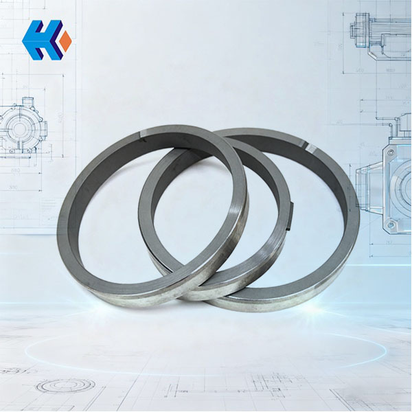
The pre-pump wear ring HZB253-640-03-04-00 manufactured by our company is specifically designed for the HZB253-640 booster pump model, fully complying with the stringent DL/T 893-2019 requirements. Our products offer superior advantages:
- Precision Fit: The tolerance between the wear ring's outer diameter and the pump casing's inner diameter is controlled within 0.05 mm, eliminating the need for further machining or grinding after welding.
- Highly Wear-Resistant Material: We employ a premium Nickel-based alloy, boosting wear resistance by over 40% and significantly extending service life.
- Standardized Welding Design: The surface of our wear rings is pre-set with spot welding location markers, guaranteeing accurate weld placement and preventing deformation due to excessive localized heat.
Related Product Recommendations: System Reliability Assurance
For optimal and sustained operation, we recommend pairing the HZB253-640-03-04-00 wear ring with the following essential components:
| Component | Model/Part Number | Reliability Function |
|---|---|---|
| Main Shaft | HZB253-640 | Ensures perfect concentricity with the wear ring and impeller, preventing eccentric wear after spot welding. Provides the foundation for stable ring operation. |
| Thrust Disc | HZB253-640A-01-02 | Absorbs axial thrust during pump operation, preventing impeller runout from striking the wear ring, thus protecting the delicate spot welds and maintaining the stable working clearance. |
| Thrust Bearing Assembly | HZB253-640A-02-05-00 | Provides stable axial support and minimizes vibration transmission during pump run-time, preventing the spot welds from cracking or loosening due to dynamic vibration. |
| Shaft Sleeve (Drive End) | HZB253-640-01-04 | Ensures accurate axial positioning of the impeller, preventing impeller displacement from binding the wear ring. Works with the wear ring to establish the required sealing clearance. |
| Lock Washer for Round Nut | HZB253-640-01-03 / HZB253-640-03-01 | Secures drive-end components and wear ring-adjacent parts, preventing looseness-induced vibration that could stress the spot welds. |
| Axial Adjusting Ring | HZB253-640-02-03 | Precisely adjusts the relative position of the bearing housing and wear ring, guaranteeing the critical working clearance (0.70–0.88 mm) is met after the ring is secured. |
| Bearing Housing Assembly | HZB253-640-02-04-00 | Offers robust support, minimizing the impact of radial vibration on the wear ring, preventing fatigue failure at the spot weld locations, and extending overall wear ring life. |
Practical Installation Guide
- Remove the old wear ring and use an angle grinder to remove the old spot welds cleanly.
- Thoroughly clean the contact surfaces of the pump casing and the new wear ring to remove all oil, grease, and rust.
- Install the new wear ring and adjust the clearance to the required 0.70–0.88 mm.
- Perform the three-point spot welding strictly following the DL/T 893-2019 standard guidelines.
- Inspect the weld and gap using a feeler gauge to confirm zero gap.
- Re-install all other components and conduct a trial run.
Proper spot welding of the pre-pump wear ring is an absolutely critical step for guaranteeing the long-term, stable operation of your pump, and strict adherence to the DL/T 893-2019 standard is mandatory. The Dongfang SRI HZB253-640-03-04-00 wear ring, combined with our full suite of recommended spares, effectively resolves all common wear ring issues, ensuring high efficiency and stability for your pre-pump and safeguarding power plant safety.
Friendly Reminder: Check your wear ring clearance every 6 months. If the gap exceeds 0.88 mm, promptly replace the ring and ensure standard spot welding is performed to prevent catastrophic performance degradation and unplanned outages.
Dongfang SRI is your professional partner for booster pump wear rings and related components, dedicated to powering safe and efficient plant operation!