


Spindle Sliding Bearing U252D06 - Deep Analysis and Solution for ID Fan Spindle Fracture


Spindle Sliding Bearing U252D06 - Deep Analysis and Solution for ID Fan Spindle Fracture
Deep Analysis and Solution for ID Fan Spindle Fracture at Ring Groove
From Fracture Mechanism to Prevention Measures, Comprehensively Guaranteeing Fan Operational Safety
During the operation of power station Induced Draft (ID) Fans, fracture at the spindle ring groove is a severe but not uncommon issue. The spindle is a key transmission component of the variable pitch vane control system, responsible for transmitting the regulating torque and supporting the weight of the control disc. Spindle fracture leads to the detachment of the control disc, causing severe dynamic imbalance. Under high-speed centrifugal force, the detached control disc violently crushes the sliders, leading to slider cracking or breakage, which subsequently triggers a chain reaction and damages other components, severely jeopardizing the unit's safe and stable operation.
Cause Analysis: Why ID Fan Spindles Fail
Spindle fracture is rarely caused by a single factor, but rather a combination of multiple elements. The primary reasons for fracture at the spindle ring groove can be grouped into the following three areas:
1. Fatigue Fracture is the Primary Mode
The spindle is subjected to complex alternating loads during operation, particularly at the ring groove where significant stress concentration occurs. Prolonged exposure to cyclic loading causes microscopic cracks to initiate and propagate within the material, eventually leading to fatigue fracture. This is the most common form of spindle failure, with the fracture surface often displaying characteristic fatigue striations.
2. Stress Concentration is the Critical Factor
The ring groove structure itself is a stress riser. If the machining quality is poor (e.g., radius of the groove bottom is too small, high surface roughness, presence of machining marks), the degree of stress concentration is further amplified. During operation, these locations are the first to develop micro-cracks that eventually expand to catastrophic failure.
3. Abnormal Loading is the Direct Inducing Factor
If the fan's guide vanes are not cycled (full open/full close) promptly after shutdown, corrosive substances like rust or ammonium bisulfate can accumulate at the blade roots, causing uneven loading on some vanes. Upon restart, these abnormal loads are transmitted through the regulating system to the spindle, highly prone to initiating fracture at the stress-concentrated ring groove.
Solutions and Steps: Systematic Response Strategy
Step 1: Emergency Response and Replacement
- Immediate Shutdown and Inspection: Immediately shut down the turbine upon any sign of spindle fracture and conduct a comprehensive check.
- Replacement of Fractured Spindle:
- New replacement spindles must be thoroughly inspected upon arrival, including verification and archiving of Certificates of Conformity, Material Certificates, and test reports.
- Prior to installation, conduct macroscopic inspection, spectral analysis, and hardness testing to ensure quality compliance.
- Strictly adhere to the required process for replacement and installation.
Step 2: Comprehensive Screening and Non-Destructive Testing (NDT)
- Fan Disassembly Inspection: Disassemble the fan in conjunction with unit overhaul procedures.
- Key Component Inspection: Conduct comprehensive Non-Destructive Testing (NDT) on critical components such as the blades and the spindle.
- Timely Defect Resolution: Promptly address or replace any discovered defects or abnormalities.
Step 3: Improvement of Operation and Maintenance (O&M) Procedures
- Establish Regular Cycling Procedure: Revise and implement a mandatory procedure for full open/full close cycling of the guide vanes after ID fan shutdown.
- Currently proposed: After ID fan shutdown, open the manhole near the motor side of the fan.
- Perform one full open/full close cycle every 6 hours.
- Observe the action of the primary and secondary vanes through the manhole.
- Temperature Monitoring: Monitor the difference between the ID fan outlet temperature and the ambient temperature.
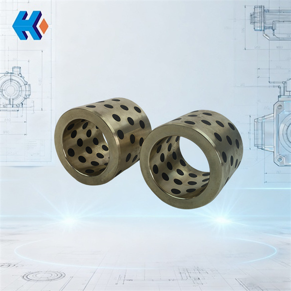
Recommended Product: Spindle Sliding Bearing U252D06
During the spindle replacement process, we highly recommend using our specially developed Spindle Sliding Bearing U252D06. This product has been specifically optimized to mitigate the issues leading to spindle fracture:
|
Feature |
Advantage |
Description |
|
Optimized Load-Bearing Structure |
Reduces Spindle Load |
Specially designed support structure effectively shares the weight of the control disc. |
|
Improved Stress Distribution |
Reduces Stress Concentration |
Unique contact surface design minimizes stress concentration points on the spindle. |
|
Enhanced Stability |
Higher Reliability |
Improved guidance structure boosts operational stability and reduces dynamic loading on the spindle. |
|
High-Strength Material |
Superior Fatigue Resistance |
Made from special alloy materials with excellent anti-fatigue properties. |
|
Wear-Resistant Coating |
Extended Service Life |
Features a special wear-resistant surface coating for long service life. |
|
Corrosion Resistance |
Harsh Environment Adaptation |
Possesses good corrosion resistance, suited for harsh operating environments. |
Operational Benefits
Replacing with the Spindle Sliding Bearing U252D06 will achieve the following:
- Effectively resolves spindle fatigue issues, enhancing equipment reliability.
- Drives (Pulls) the control disc, ensuring regulation flexibility.
- Supports the control disc's weight, reducing stress on the spindle.
- Withstands dynamic loads generated by control disc vibration, improving system stability.
Preventive Maintenance Recommendations
- Regular Inspection: Establish a regular spindle inspection regimen (recommended every $\mathbf{10,000}$ operating hours for a comprehensive check).
- Condition Monitoring: Install vibration monitoring devices for real-time tracking of the spindle's operating status.
- Preventive Replacement: Schedule periodic preventive replacement of the spindle and bearing based on operating hours and technical condition.
- Operational Optimization: Optimize start-up and shut-down procedures to minimize the occurrence of abnormal loads.
Summary Recommendations
A systematic approach is essential to address ID Fan spindle fracture:
- Act Immediately: Shut down immediately upon detecting an anomaly to prevent accident escalation.
- In-Depth Analysis: Determine the fracture nature (e.g., fatigue) through fractography to find the root cause.
- Comprehensive Improvement: Optimize all aspects: design, manufacturing, installation, and operation.
- Professional Selection: Choose high-quality spindles and the Spindle Sliding Bearing U252D06.


