DTYJ60FM001 Induced Draft Fan Side Coupling to Main Shaft


Today, we will detail the connection method of the DTYJ60FM001 Fan-Side Coupling to the main shaft, aligning with the design features of mainstream adjustable blade axial flow ID fans and ensuring compliance with the transmission system stability requirements of GB/T 1236-2017 (Industrial Fans – Performance Testing).
First, it is crucial to recognize that the fan-side coupling connection must simultaneously satisfy three core requirements: Precise Alignment, Stable Torque Transmission, and Anti-Loosening/Anti-Slip. The prevailing solution is a compound connection utilizing "Tapered Interference Fit + Keyway Torque Transmission + Shaft-End Nut Fastening."
The DTYJ60FM001 Fan-Side Coupling is specifically optimized for this solution, guaranteeing connection reliability through superior component precision.
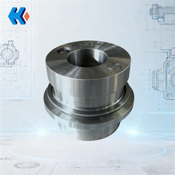
Step 1: Tapered Interference Fit
The hub bore of the DTYJ60FM001 Fan-Side Coupling is manufactured using high-precision CNC machining. This guarantees the concentricity between the coupling and the main shaft, thereby minimizing vibration sources. This design fully adheres to the precision requirements for transmission components outlined in GB/T 1236-2017, laying the foundation for the subsequent steps.
Step 2: Keyway Torque Transmission
Relying solely on the tapered fit is often insufficient to handle the full torque output from the motor. Both the inner bore of the DTYJ60FM001 Fan-Side Coupling and the corresponding position on the main shaft are machined with standard keyways.
When assembled, after embedding the parallel key, the clearance between the key allows for efficient torque transmission while preventing damage to the mating surfaces caused by excessive tightness.
Critical Note: Before installation, use a cleaning agent to remove any oil, grease, or burrs from the keyway to ensure the parallel key seats fully and flatly. This is the crucial step in preventing relative rotation.
Step 3: Final Anti-Loosening with Shaft-End Nut
After completing the tapered fit and keyway installation, a specialized hydraulic tool must be used to tighten the shaft-end nut. The flange face of the DTYJ60FM001 is designed with a dedicated nut locating groove to ensure uniform force application during tightening.
Recommendation: Pre-tighten the nut to 85% of its rated bolt torque. This final step eliminates any micro-clearances in the tapered fit and prevents connection loosening caused by vibration during operation.
Comprehensive Component Support for Auxiliary Equipment Reliability
Choosing the DTYJ60FM001 means selecting a reliable and durable "power joint" for your ID fan, effectively resolving vibrations and failures stemming from coupling quality issues. We are committed to providing comprehensive spares support, including:
- Bearing Sealing Components: Oil Scraper Ring (TY9111C), Oil Collector Ring (UZ22016), and Seal Ring (HU27452-22G).
- Hydraulic Adjustment System Parts: Disc Springs (UZ22000(DY), UZ22015) and Exhaust Gasket.
- Condition Monitoring: Dual RTD Thermometer (W1 U236D00(DY)).
- Cooling & Conveying: Cooling Fan (TY8000) and CPMW Scraper II Conveying Component.
Post-Installation Check
Finally, after installation, manually bar the fan to check for smooth rotation of the DTYJ60FM001 Fan-Side Coupling. Upon startup, monitor the vibration levels. Should any sign of loosening appear, prioritize checking the shaft-end nut pre-tightening force and the keyway fit condition.