


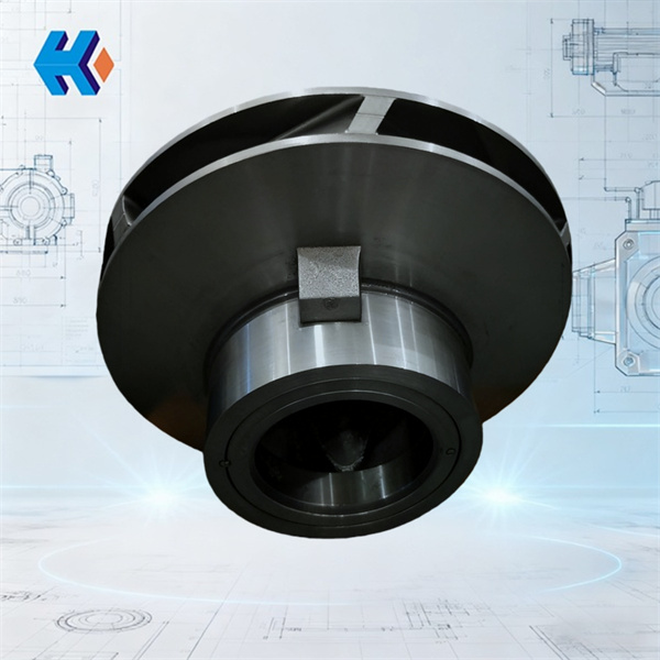
Key Steps and Operational Essentials for Disassembling ID Fan Impeller HU25040-22G-08


The HU25040-22G-08 ID fan impeller is a core component of axial fans. Standardized disassembly directly impacts the quality of subsequent maintenance. Based on years of power station maintenance experience, we have outlined the following practical operational points and procedures.
I. Core Disassembly Steps
-
Preparation: Verify the compliance of lifting equipment, clear the workspace, and designate specific areas for component storage.
-
Removal of Pipelines and Static Components:
-
Disconnect and label all connected pipes and measurement points; seal interfaces to prevent foreign object ingress.
-
Remove the insulation layer and the flexible connections of the diffuser.
-
Adjust the blades to the fully closed position, then remove the bolts from the horizontal split plane of the casing and hoist away the upper half of the casing.
-
-
Impeller Separation:
-
Remove the end components of the inlet guide vane (IGV) core cylinder.
-
Support the intermediate connecting shaft, loosen the half-coupling, and remove the coupling after localized heating.
-
Secure the impeller using steel wire ropes attached to 4–5 blades within the upper 45° sector.
-
Remove the pressure plate bolts and slide the impeller out axially.
-
II. Key Operational Essentials
-
Blade Condition Inspection: Before disassembly, inspect blades for wear and cracks. If weld wear exceeds 1/4 of the thickness, replacement is mandatory. Note that the HU25040-22G-08 impeller by HuaKai ShengRui utilizes reinforced welding processes for superior wear resistance.
-
Lifting Standards: Maintain the impeller in a horizontal position during hoisting. Ensure the wire ropes do not squeeze the blades and that lifting points are distributed evenly to prevent deformation. (These impellers undergo rigorous dynamic balancing, offering higher tolerance during handling).
-
Component Protection:
-
Number and mark all disassembled parts clearly.
-
Place the impeller on wooden sleepers to avoid direct contact with the ground.
-
Apply anti-rust oil to shaft components and seal all interfaces.
-
-
Safety Control: Work must only begin after the fan has come to a complete standstill and the power is locked out. Removing protective devices while the unit is rotating is strictly prohibited. Warning signs must be displayed at the site.
III. Spare Parts Replacement Recommendations
If the impeller exhibits cracks, severe erosion, or exceeds dynamic balance limits, replacing it with a spare is recommended. The HuaKai ShengRui HU25040-22G-08 impeller strictly adheres to the DLT748.5-2001 standard. It features:
-
High-compatibility design for the same axial fan models.
-
Wear-resistant blade materials.
-
Multi-stage NDT (Non-Destructive Testing) before leaving the factory.
-
Significant reduction in vibration failure rates post-installation, enhancing overall operational stability.
-
Component Name Model Primary Application & Description Stage II Impeller U236Y200 Performs work in the second stage of dual-stage axial fans to enhance pressure efficiency. Fork Connecting Pin TY9614 Connects the adjustment mechanism to the blade fork; transmits adjustment torque. Elastic Pin Coupling YI35556 Compensates for minor shaft misalignments, provides damping and buffering to ensure smooth transmission. Inlet Guide Vane (IGV) Control Unit A370T00 Controls the opening angle of the IGVs to optimize the airflow entry angle. Lifting Lug (Ear Plate) A350Z01 Used for positioning and auxiliary hoisting of the casing or support frames. Slide Block LG232213A Installed within the adjustment mechanism to enable smooth blade angle modulation. Inlet Seal Gasket A350P11 Prevents external air leakage to improve overall fan efficiency. Cooling Fan TY8000 Used for forced cooling of the motor or bearing housing to ensure controlled temperature rise. Coupling GI34546 Connects the fan main shaft to the drive motor for torque transmission.
HKZX-2026-01-05


