Mechanical Seal Sleeve FAID56-01-07: 3 Essential Pre-Installation Checks and Technical Analysis


Today, we focus on high-frequency replacement sleeves in industrial settings, dissecting the technical essentials of the entire installation process. We will examine the characteristics of over a dozen commonly worn sleeves and, through practical cases from us, explore how detail optimization can solve the pain point of "frequent replacement."
I. Before Installation: Precise Fitting is the First Step to Extending Lifespan
Many site operations and maintenance (O&M) personnel encounter the problem of a "sleeve wearing out immediately after replacement." The root cause often lies in the pre-installation fit-check stage. The key inspection points vary completely depending on the sleeve's application:
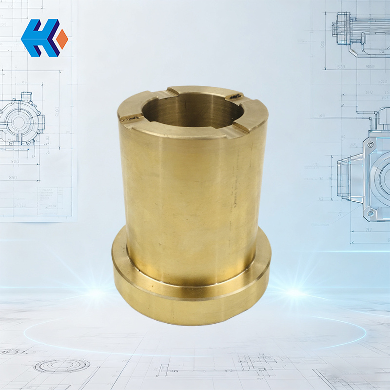
For the FA1D56-01-07 mechanical seal sleeve, commonly used in the booster pump of a boiler feed pump, which cooperates directly with the mechanical seal ring, there are 3 essential pre-installation checks:
- Check 1: Clearance Fit Conformance (H7/h6 Standard)
A feeler gauge must be used to confirm that the fit clearance between the sleeve and the mechanical seal ring complies with the H7/h6 standard. - Check 2: Outer Diameter Surface Integrity (Micro-damage)
Carefully inspect the sleeve's outer diameter—even minor nicks or scratches from transport can lead to seal leakage. This leakage then erodes the sleeve, accelerating wear. - Check 3: Inner Bore Condition (Rust/Burrs)
The inner bore must be polished with fine sandpaper to remove any rust and burrs. This prevents scratching the shaft journal during assembly, which could create a hidden wear hazard.
For sleeves used in transmission systems, such as the FA1D56-01-05 (transmission end outer sleeve) and FA1D56-01-06 (transmission end inner sleeve), the focus is on checking the interference fit with the transmission shaft. The interference fit is generally required to be between 0.02-0.05mm. Insufficient interference will cause "slippage" during operation; excessive interference can lead to sleeve deformation after assembly.
For common sleeves in general fluid machinery, such as 300MG41.11.09S and FA1D56-103, wall thickness uniformity is the critical inspection item. Measure the circumference at 6 points using a micrometer; the deviation must be controlled within 0.03mm. Especially in high-pressure applications, non-uniform wall thickness leads to localized stress concentration, causing deformation and failure in a short time.
Case Study: A power plant previously reported that the front sleeve of their coal mill motor (YMKQ500-6) had to be replaced monthly. The technical team found that the user never checked the roughness of the sleeve's datum surface before installation. This sleeve requires a surface roughness of Ra1.6, but the actual delivered sleeve only had Ra3.2. After assembly, the coaxiality deviation with the motor bearing seat reached 0.12mm, causing single-sided force and wear on the sleeve during operation. us subsequently provided a "pre-check service," testing critical parameters upon arrival and immediately replacing non-compliant products. The sleeve replacement cycle at this plant was extended from 6 months to 12 months, significantly improving O&M efficiency by reducing frequent shutdowns.
For coal mill roller system sleeves, such as the 20MG30.11.09.84J roller sleeve and the 20MG32.11.09-35 sleeve, which operate under conditions with high dust and impact, the integrity of the wear-resistant layer (such as tungsten carbide coating) must be the focus of the pre-installation check. If any coating peeling or scratching is found, even in a small area, the sleeve must be replaced in advance—wear will rapidly spread from the damaged coating area, leading to eccentric wear of the roller and potential damage to other components.
For the JLX25Z-1001/07-01 input shaft sleeve used in power input systems, keyway fit is core. Before installation, confirm the clearance between the sleeve keyway and the input shaft key is between 0.01-0.03mm. Excessive clearance easily causes "slippage" during operation, which not only wears the sleeve but also affects power transmission efficiency; insufficient clearance increases assembly difficulty or can even cause the sleeve to crack.
II. During Installation: Focus on Key Operations Based on Sleeve Characteristics
Detail control during the installation process directly determines the sleeve's service life. The operational essentials vary significantly for different types of sleeves. We'll examine them based on specific models:
(I) Transmission System Sleeves: Controlling "Axial Float and Eccentric Wear"
Taking FA1D56-01-05 and FA1D56-01-06 as examples, these sleeves are the "connection hubs" of the transmission system. Installation must follow the principle of "inner first, outer later, and stepped pressing":
- First, install the inner sleeve FA1D56-01-06 using a hydraulic press at a constant speed with 5-8MPa pressure. During the pressing process, a dial indicator must monitor the fit between the sleeve end face and the shaft shoulder in real-time to ensure the clearance is ≤0.02mm. If the fit is not tight, axial float will occur during operation.
- Next, install the outer sleeve FA1D56-01-05. Note that the end face clearance with the inner sleeve must be controlled at 5-8mm (adjust according to the equipment drawings). This gap is to reserve space for thermal expansion and contraction, preventing mutual squeezing and deformation when the temperature rises.
- Finally, tighten the fixing bolts (typically M16-M20) of the outer sleeve. They must be tightened in a "diagonal, layered" sequence, with a torque value referenced at 35-45N・m (adjust according to sleeve specifications). Do not fully tighten in one go, as this prevents sleeve deformation due to excessive localized force.
(II) Coal Mill Sleeves: Addressing "Harsh Conditions"
Due to the harsh conditions of coal mills, installation of 20MG30.11.09.84J, 20MG32.11.09-35, and YMKQ500-6 sleeves must focus on solving "wear resistance" and "vibration resistance":
- When installing the 20MG30.11.09.84J roller sleeve, a high-temperature wear-resistant grease (molybdenum disulfide-based grease recommended) must be uniformly applied between the sleeve and the roller shaft, with a thickness controlled at 2-3mm. This grease layer not only reduces assembly resistance but also forms a stable oil film during operation, blocking dust ingress and preventing rapid wear from dry friction. Concurrently, the retaining rings at both ends of the sleeve must be correctly installed and fixed with dowel pins to prevent dust from entering the sealing cavity and contaminating the lubricant.
- When assembling the YMKQ500-6 motor front sleeve, the "temperature difference method" is recommended: preheat the sleeve in 80-100℃ hot oil for 15-20 minutes. Note that the heating rate must be ≤5℃/min to avoid sleeve deformation from sudden temperature increases. After removal, quickly fit it onto the motor journal. After natural cooling, use a dial indicator to check the sleeve's radial runout, which must be ≤0.05mm. If the runout exceeds the tolerance, severe vibration will occur when the motor operates, causing the sleeve's outer diameter to rub against the bearing seat repeatedly, drastically shortening its life.
(III) General and Sealing Sleeves: Strict Control of "Fit Clearance"
For the FA1D56-01-07 and FA1D56-01-07-17 sleeves of the feed pump booster pump, and the 300MG41.11.09S and FA1D56-103 sleeves of general fluid machinery, "clearance control" during installation is key:
- For FA1D56-01-07 and FA1D56-01-07-17, the fit clearance with the mechanical seal ring must be checked point by point. Use a feeler gauge at 8 evenly distributed points on the circumference; the difference in clearance between any two points must be ≤0.01mm. If the clearance is uneven, localized leakage will occur in the seal cavity. The high-pressure fluid will scour the sleeve's outer diameter, quickly forming noticeable wear grooves.
- After installing the 300MG41.11.09S and FA1D56-103 sleeves, a laser alignment tool must be used to check the coaxiality between the sleeve and the housing, with a required deviation of ≤0.03mm. If the coaxiality is out of tolerance, the sleeve will be subjected to radial forces during operation, not only accelerating its own wear but also causing bearing heating, abnormal noise, and triggering a cascade of failures.
us Case Study: The JLX25Z-1001/07-01 input shaft sleeve at a chemical plant frequently failed, requiring replacement 2-3 times per month. The technical team observed that operators struggled to align the sleeve keyway precisely during installation, and repeated adjustments led to uncontrolled fit clearance. Simultaneously, conventional feeler gauges lacked the necessary precision. To address this, us added "positioning scribes" to the sleeve's inner wall to guide site personnel in quickly aligning the keyway. They also custom-made a special feeler gauge with 0.001mm precision for real-time clearance measurement. Following optimization, the sleeve replacement cycle was extended to 4 months, and installation time was reduced from 2 hours to 40 minutes, significantly reducing the O&M team's workload.
III. After Installation: Inspection and Documentation are Essential
After sleeve installation, the equipment cannot be immediately put into operation. Strict testing must be conducted to eliminate potential hazards, and detailed documentation is essential for future O&M. Although the inspection focus varies for different sleeves, the core process can be summarized as "3 Mandatory Tests + 1 Record Log":
- 1. Radial Runout Test: For all sleeve types, use a dial indicator to measure 4 points each on the outer diameter (at the 1/2 point) and the end face. Sleeves for coal mills, such as 20MG30.11.09.84J and 20MG32.11.09-35, have stricter requirements, with runout ≤0.03mm. Sleeves like FA1D56-01-07 and 300MG41.11.09S require runout ≤0.05mm. If runout exceeds tolerance at any point, the assembly steps must be re-checked to eliminate coaxiality or fit clearance issues.
- 2. Sealing Performance Test: For sleeves with sealing structures, such as FA1D56-01-07 and FA1D56-01-07-17, a sealing performance test must be conducted. Pressurize with 0.3-0.5MPa of compressed air and maintain the pressure for 5 minutes. The leakage rate is required to be ≤5mL/min. If the leakage rate is exceeded, check the fit between the sealing ring and the sleeve or replace the damaged sealing components to prevent leakage during operation.
- 3. No-Load Trial Run: Run the equipment at no load for 30 minutes. Use an infrared thermometer to check the sleeve temperature, which must be ≤70℃ for all models. Simultaneously, use a stethoscope to listen to the operational sound; no abnormal noise indicates compliance. If excessive temperature or abnormal noise occurs, immediately shut down the machine and check for issues such as sleeve deformation or overly tight fit.
- O&M Record Log: Detail the sleeve model (e.g., FA1D56-01-05, JLX25Z-1001/07-01, etc.), installation date, test data, and installer information. us provides users with an "Electronic O&M Log" where data can be entered by scanning a code. This facilitates future inquiries into sleeve service life and allows for the proactive formulation of spare parts purchase plans based on the replacement cycle, preventing shutdowns due to missing parts.
Summary: The Core Logic from "Frequent Replacement" to "Long-Term Stability"
While the over a dozen types of wear-prone sleeves we've dissected—including FA1D56-01-07, YMKQ500-6, and JLX25Z-1001/07-01—have different applications and technical requirements, the core logic for extending their lifespan is consistent: Precise fitting before installation, strict control of details during installation, and comprehensive testing after installation.
The installation cases shared fully demonstrate that "frequent sleeve replacement" is not an unsolvable problem. By optimizing inspection processes, providing customized tools, and perfecting O&M records, sleeve life can be significantly extended, while also reducing "ineffective labor" for site personnel, freeing them from tedious, repetitive replacement work to focus on core equipment management and optimization.