


Deep Analysis & Solutions: TY96010 Hydraulic Cylinder Linkage Failure in Adjustable Axial Fans
Deep Analysis & Solutions: TY96010 Hydraulic Cylinder Linkage Failure in Adjustable Axial Fans
The sudden fracture of the TY96010 Hydraulic Cylinder Linkage in the variable-pitch axial flow fan of a specific 300MW power plant unit (e.g., owned by China Power Investment Corporation) is a serious, though not uncommon, issue. This failure not only leads to the loss of fan regulation capability and unstable operation but also severely impacts the overall stability and safety of the unit, resulting in significant economic losses from unplanned shutdowns. Such incidents have a certain degree of universality in the electric power generation sector. Systemic analysis indicates that the primary causes leading to this problem are concentrated in the following three aspects:
Root Cause Analysis of TY96010 Linkage Fracture
Based on field experience, linkage fracture is rarely caused by a single factor; it is usually the result of a combination of multiple stresses. Here are the two most crucial contributing factors:
1. Extreme Stress Under Abnormal Conditions (Direct Trigger)
This is the most common cause. The problem begins when both oil pumps in the induced draft fan (ID fan) hydraulic oil station trip (lose power) simultaneously, while the ID fan itself continues to rotate due to inertia. At this moment, the immense centrifugal force acting on the fan blades generates a powerful closing torque, which rapidly increases. The servo valve struggles to counteract this torque to maintain the current pitch opening, requiring excessively high pressure. When the servo valve eventually leaks pressure, the hydraulic cylinder linkage group suddenly and violently acts to decrease the pitch angle. This severe impactive load is extremely likely to cause the linkage to fracture.
2. Improper Operation and Missing Protection Logic (Fundamental Cause)
In a critical situation where the oil pumps are completely stopped and system pressure is already lost, attempting to restart a hydraulic oil pump without taking any protection measures (such as an emergency fan shutdown) is a typical operational error that leads to catastrophic failure. This action is equivalent to suddenly applying a tensile force from one side while the linkage is already under immense compressive stress. This "squeeze-and-pull" action instantly pushes the stress far beyond the design limit, causing the linkage to yield and fracture. The fundamental cause lies in imperfect thermal control protection logic, which fails to effectively block such dangerous operations.
Systemic Solution for TY96010 Failure: Procedure and High-Strength Replacement
To effectively address this issue, a systematic solution is required, moving beyond mere symptomatic fixes.
Step 1: Optimize Operating Procedures
Clearly formulate emergency handling procedures after a complete hydraulic oil pump failure. The core principle is: prioritize equipment safety over blindly rushing recovery. Suggested procedures are as follows:
- Immediately confirm hydraulic oil pressure upon complete oil pump failure.
- Set the low oil pressure alarm for the ID fan control oil pressure at 3.2 MPa. If the pressure drops below this value, start the standby pump after a 15-second delay.
- If, after the standby pump starts, the pressure remains below the 3.2 MPa alarm value after a 30-second delay, the fan must be immediately tripped (shut down). This is the most crucial step; do not rely on chance.
- Only after the fan is shut down should a thorough inspection and overhaul of the hydraulic oil station be performed.
Step 2: Refine Thermal Protection Logic (Long-Term Fix)
To eradicate the risk at the system level, the control logic in the DCS or PLC must be upgraded:
- Add Trip Protection: Integrate a logic that uses the "both hydraulic oil pumps tripped" or "hydraulic oil level low-low" signals to directly trigger a trip of the ID fan and a Runback (RB) action. This sets an inviolable safety boundary for the system.
- Implement Operational Interlocks: Introduce logic: "If both hydraulic oil pumps are tripped, lock out executive mechanism opening." This effectively prevents misoperation of the servo valve when pressure is insufficient, avoiding secondary damage to the cylinder and linkage.
Step 3: Install High-Strength Spares and Establish Preventive Maintenance
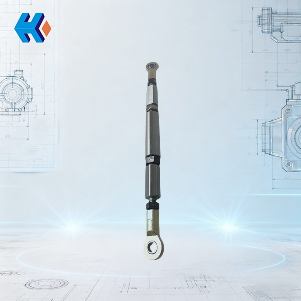
After completing the above steps, replacing the fractured linkage is the final execution phase. I highly recommend using our company's TY96010 High-Strength Hydraulic Cylinder Linkage.
This product has been specially reinforced to mitigate the failure mechanisms described above:
- Material Upgrade: Utilizes high-strength alloy steel with specialized heat treatment, providing significantly higher tensile and fatigue strength than standard products, allowing it to physically withstand greater impact loads.
- Process Optimization: The surface undergoes precision grinding and anti-corrosion treatment, and critical stress concentration areas feature a rounded-edge design, greatly enhancing fatigue life.
- Reliability Verification: Every linkage undergoes flaw detection and load testing before leaving the factory to ensure it meets the most demanding operating conditions
HKZX-2025-10-20-A


-
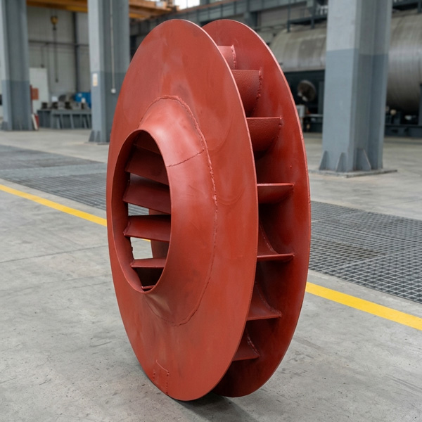
Looking at Abnormal Wear on U250-Y01 Induced Draft Fan Moving Blades
Understand why U250-Y01 induced draft fan blades wear out and how to maintain mechanical linkages. We provide U250-Y01 blades, seals, and connecting rods.03-23
-
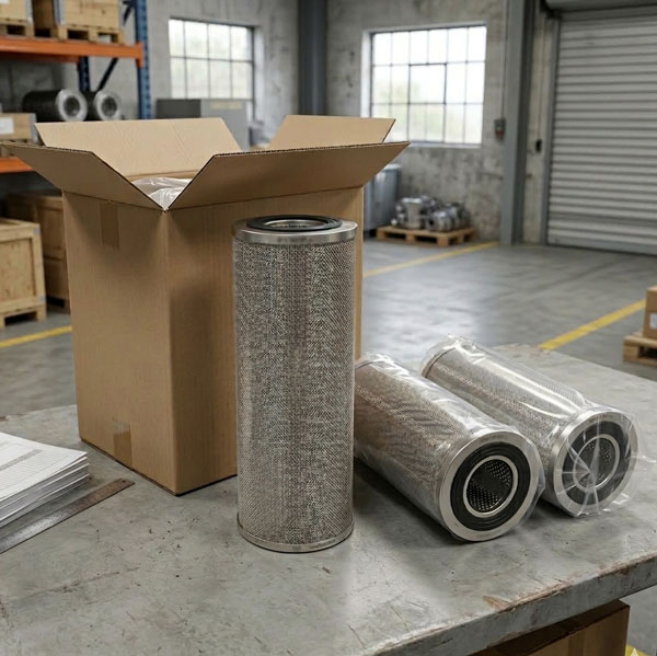
Easy Maintenance with the SDGLQ-60T-36K Duplex Oil Filter for Coal Mills
Learn how to switch the SDGLQ-60T-36K duplex filter element without stopping your coal mill. No oil flow interruption, stable pressure, and zero bypass. Get a quote today.03-17
-
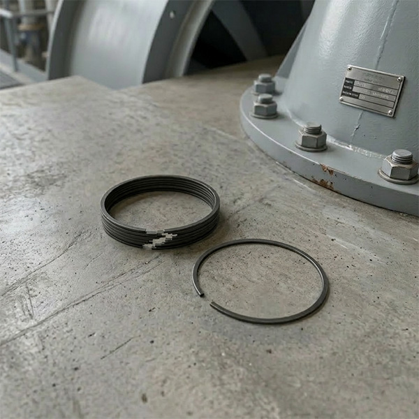
Keeping Your ID Fan Safe with the U2616G2106Y01 Blade Seal Ring
Protect your HU25042-221G fan with the U2616G2106Y01 blade seal ring. Learn how multi-stage sealing prevents bearing jams, blade sticking, and fan stalls.03-12
-
Stopping Oil Leaks with the UYG35/20G010 ID Fan Seal Ring
Stop bearing box leaks with the UYG35/20G010 ID fan seal ring. Learn how gap control and thermal expansion prevent grip failure in induced draft fan spare parts.03-11
-
How to Detect Micro Leakage in Feed Water Pump Gasket FA1D56-03-09 Before It Causes Shutdown
Learn the common failure modes of feed water pump cooling water jacket sealing gasket FA1D56-03-09, including aging, creep relaxation, and mechanical damage. Understand external signs, micro leakage detection methods, and practical maintenance tips to prevent pump shutdown and reduce repair cost.03-02


