


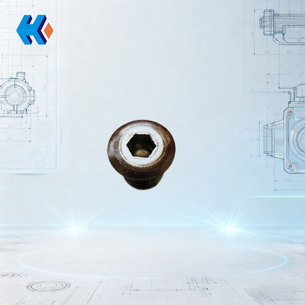
Hydraulic Coupling Fusible Plug CO46-02-12A: Fortifying the Safety Line for Power Plant
In power plant dynamic systems, overheating in a CO46 hydraulic coupling due to overload or jamming can lead to minor issues like equipment shutdown or major failures such as motor burnout and component scrap. The custom-made CO46-02-12A Hydraulic Coupling Fusible Plug has become available for bulk supply. With its core performance of "Precise Melting, Instantaneous Protection," it is now a "Life-Saving Component" that ensures the safe operation of critical power plant equipment like feedwater pumps and fans. We offer both in-stock and customized services, solving the urgent need for spare parts during power plant maintenance.
I. Product Positioning: The "Overheat Safety Valve" for CO46 Hydraulic Couplings
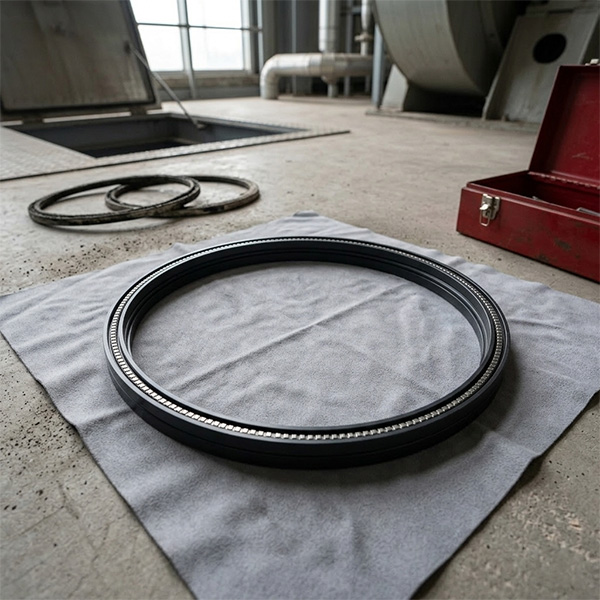
The CO46-02-12A fusible plug is not a regular spare part; it is the core safety protection device for the CO46 hydraulic coupling. When power loss converts into heat due to operating conditions like braking or a sudden load increase, causing the working fluid temperature in the coupling chamber to surge, this fusible plug uses the precise melting of its internal fusible alloy to timely interrupt power transmission, fundamentally preventing equipment damage from overheating.
As a "must-check, must-replace" component during power plant maintenance, its actuation temperature is strictly set below the flash point of the coupling's working fluid, completely eliminating the risk of fire or explosion caused by fluid overheating. The head of the equipment department at a thermal power plant stated: "We previously had a coupling overheat due to a fusible plug failure, resulting in maintenance costs of over 200,000 yuan. Now, we prioritize replacing the CO46-02-12A during every maintenance cycle. It's like adding 'double insurance' to the equipment."
II. Three Core Advantages: Precision, Reliability, and Durability
1. Structural Design: Zero-Delay Temperature Sensing
The plug body features a stepped through-hole, and the filling amount of the internal fusible alloy is calculated based on fluid dynamics to ensure "instantaneous conduction" of temperature changes. Crucially, it is strictly designed to be installed at the point of the largest internal diameter of the coupling chamber. This location directly captures the true temperature of the working fluid, preventing "protection delay" caused by installation position deviations, achieving a 40% faster reaction speed compared to non-specialized fusible plugs.
A special note: This fusible plug must never be installed in the filling port, nor should it be replaced with a standard screw plug or fixed by welding. Incorrect use will directly negate the protection function, a critical point for power plant operation and maintenance.
2. Protection Principle: Millisecond-Level Power Interruption
When the temperature of the coupling's working fluid reaches the melting point of the fusible alloy, the alloy melts precisely, creating a pressure-relief channel. The working fluid is then rapidly expelled by centrifugal force, and the coupling, having lost its medium, can no longer transmit power and instantly stops working. The entire process takes only 0.8 to 1.2 seconds, effectively preventing irreversible damage such as motor overload burnout and coupling casing deformation, thus protecting downstream equipment.
3. Material Characteristics: Robust Durability Reduces Cost
The plug body is made from high-hardness, wear-resistant alloy, capable of withstanding fluid scouring and vibration during the coupling's high-speed rotation. Its anti-corrosion and anti-wear properties far surpass ordinary steel, offering a service life of up to 24 months—1.5 times that of traditional fusible plugs. The internal fusible alloy composition has undergone over 200 melting point tests, ensuring consistent protection across different working conditions and reducing repeated maintenance caused by part failure.
III. Technical Specifications Table: Key Parameters at a Glance
| Item | Specification Details | Notes |
|---|---|---|
| Product Model | Hydraulic Coupling Fusible Plug CO46-02-12A | Custom-designed for CO46 hydraulic couplings |
| Applicable Equipment | CO46 Series Hydraulic Couplings | Adapts to power equipment like power plant water pumps, fans |
| Fusible Alloy Melting Point | Standard 125℃; Custom 140℃ | Customizable based on the working fluid type |
| Temperature Matching Requirement | Actuation temperature < Working fluid flash point | Requires confirmation of fluid model beforehand |
| Installation Location | Point of largest diameter in the coupling inner chamber | Strictly forbidden to install in the fluid filling port |
| Plug Body Material | Wear-resistant, anti-corrosion alloy | Tolerates high-speed fluid scouring |
| Structural Features | Stepped through-hole design, precise fusible alloy filling | Ensures zero-delay temperature conduction |
IV. Application Scenarios: Covering All Power Plant O&M Situations
1. Routine Operation: Real-Time Prevention of Sudden Risks
During the operation of power plant equipment such as water pumps and fans, if an impeller jam or pipeline blockage causes a sudden increase in coupling load, the CO46-02-12A fusible plug will immediately activate protection, preventing the equipment from "running under fault". A power plant once averted a major loss—motor scrap—when a fan bearing seizure triggered the fusible plug, allowing recovery simply by replacing the fluid and the plug.
2. Scheduled Maintenance: Essential Replacement Safety Spare Part
During annual or quarterly power plant maintenance, technicians prioritize checking this fusible plug. If the plug body shows corrosion or the alloy has cracks, it is replaced immediately. Especially for couplings that have experienced overload impact, the plug is replaced even if it hasn't actuated, ensuring complete protection capability upon equipment restart.
3. Post-Fault Recovery: Rapid Safety Barrier Reconstruction
When a coupling is repaired after an overheating failure, the newly replaced CO46-02-12A fusible plug serves as the "final safety check". It must be replaced along with the coupling working fluid to ensure the protection temperature matches the fluid's flash point, preventing protection failure due to incompatible fluid types.
V. Core Spare Parts Table for Power Plant Dynamic Equipment
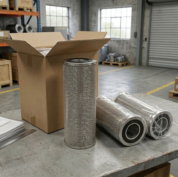
To meet the power plant demand for "Single Purchase, Comprehensive Maintenance", we simultaneously supply core spare parts compatible with the CO46-02-12A fusible plug for feedwater pumps. All items are stocked in inventory and can be ordered and replaced concurrently with the fusible plug, significantly boosting maintenance efficiency:
| No. | Part Model | Part Name | Applicable Scenario | Relevance to CO46-02-12A Fusible Plug | Notes |
|---|---|---|---|---|---|
| 1 | DG750-180-01-06 | Washer | Feedwater pump flange sealing | Ensures pump sealing, jointly maintains dynamic system stability with the fusible plug | High-pressure, high-temp resistant |
| 2 | HPT300-340-01A-08 | Nut | Feedwater pump component fixation | Ensures secure component mounting, prevents vibration from affecting fusible plug protection accuracy | High-strength, anti-loosening design |
| 3 | FA1B56-A2-102761A | Oil Deflector Ring | Feedwater pump bearing chamber oil control | Prevents lubricant leakage from contaminating coupling working fluid, indirectly securing fusible plug operation | Wear-resistant alloy material |
| 4 | DG600-240-05-11 | Pump Seal | Feedwater pump shaft end seal | Blocks media leakage from pump, forms "dual sealing protection" with the fusible plug | Combination seal structure |
| 5 | FK5G32-04-12 | Radial Bearing | Feedwater pump rotor support | Guarantees stable pump rotation, reduces coupling load fluctuation, lowers fusible plug trigger frequency | High-precision, low-friction coefficient |
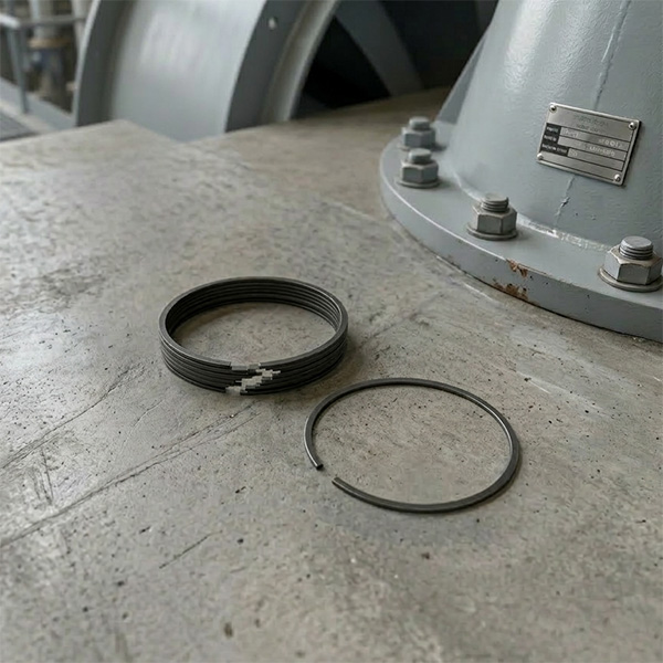
| 6 | DG600-240-07-02(2) | Seal Ring Backing Ring | Feedwater pump seal ring positioning | Fixes seal ring position, prevents seal failure leading to pump fault, easing coupling pressure | Corrosion-resistant stainless steel |
| 7 | HZB253-640-01-11 | Lock Nut | Feedwater pump impeller fixation | Prevents impeller loosening causing sudden load changes, reducing overload protection pressure on the fusible plug | Anti-disengagement design |
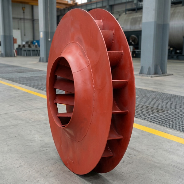
| 8 | FT12R33M-03-03 | Impeller | Feedwater pump media conveying | Optimizes water flow field, reduces pump energy consumption, stabilizes coupling load | Streamlined high-efficiency design |
| 9 | HPT200-330-04-13 | Second-stage Guide Vane | Feedwater pump media flow guidance | Balances internal pump pressure, prevents pressure fluctuation from affecting coupling operation | Precision hydraulic model design |
| 10 | HTHP-01-02-19-04 | Horizontal Split Surface Nut | Feedwater pump casing joint sealing | Ensures casing joint sealing, prevents media leakage causing system failure | High-strength torque adapted |
| 11 | HZB330-790A | Steam Pump Booster Pump Thrust Pad | Steam pump booster pump axial force balance | Guarantees stable booster pump operation, prevents feedwater pump supply fluctuation, indirectly stabilizing coupling condition | Babbitt alloy coating |
VI. Procurement and Service Support: Customized Solutions for Non-Standard Spares
To address the challenges of hard-to-find spare parts for older power plant equipment and the unsuitability of standard spares for special operating conditions, our company possesses professional "Process-by-Drawing" capabilities. We offer full-process customization services focused on the CO46-02-12A fusible plug and the aforementioned feedwater pump spare parts. Whether based on plant-provided equipment drawings, old part measurement data, or material and structural optimization for special conditions (such as customizing the fusible plug alloy melting point or upgrading the pump seal's anti-corrosion coating for high-temperature/high-corrosion environments), we can achieve precise processing.
During the processing, our technical team first conducts an in-depth analysis of the drawings, confirming key parameters (such as the fusible plug through-hole size, bearing precision grade), and offers material selection suggestions. Simultaneously, we implement full-process quality control, from raw material testing and processing precision calibration to finished product performance testing. A test report is generated for every step, ensuring the customized spare part perfectly matches the original equipment and performs no less than the original factory standard.
To inquire about our process-by-drawing solutions, submit drawing requirements, or obtain technical specification sheets for customized spare parts, please contact us directly. We provide exclusive support for the operation and maintenance of specialized power plant equipment.


-
Looking at Abnormal Wear on U250-Y01 Induced Draft Fan Moving Blades
Understand why U250-Y01 induced draft fan blades wear out and how to maintain mechanical linkages. We provide U250-Y01 blades, seals, and connecting rods.03-23
-
Easy Maintenance with the SDGLQ-60T-36K Duplex Oil Filter for Coal Mills
Learn how to switch the SDGLQ-60T-36K duplex filter element without stopping your coal mill. No oil flow interruption, stable pressure, and zero bypass. Get a quote today.03-17
-
Keeping Your ID Fan Safe with the U2616G2106Y01 Blade Seal Ring
Protect your HU25042-221G fan with the U2616G2106Y01 blade seal ring. Learn how multi-stage sealing prevents bearing jams, blade sticking, and fan stalls.03-12
-
Stopping Oil Leaks with the UYG35/20G010 ID Fan Seal Ring
Stop bearing box leaks with the UYG35/20G010 ID fan seal ring. Learn how gap control and thermal expansion prevent grip failure in induced draft fan spare parts.03-11
-
How to Detect Micro Leakage in Feed Water Pump Gasket FA1D56-03-09 Before It Causes Shutdown
Learn the common failure modes of feed water pump cooling water jacket sealing gasket FA1D56-03-09, including aging, creep relaxation, and mechanical damage. Understand external signs, micro leakage detection methods, and practical maintenance tips to prevent pump shutdown and reduce repair cost.03-02


