


Critical ID Fan Maintenance: Why Sealing the Outlet Damper is Non-Negotiable When Replacing Actuator Link Rods DTYD100UI002
Critical ID Fan Maintenance: Why Sealing the Outlet Damper is Non-Negotiable When Replacing Actuator Link Rods DTYD100UI002
The Hidden Risk: Overlooking ID Fan Outlet Damper Sealing
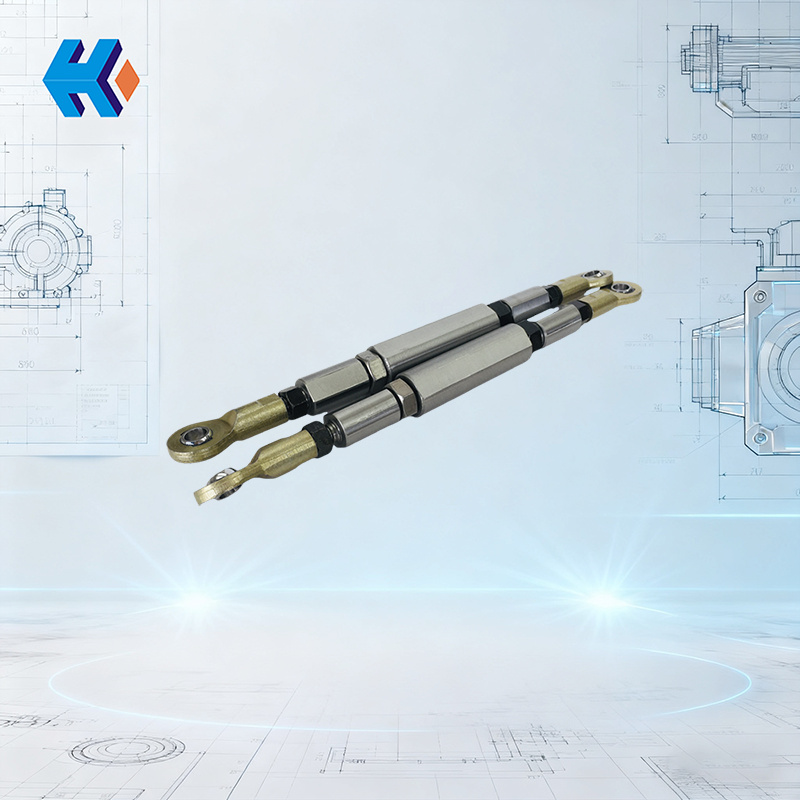
When performing maintenance on a broken fan actuator link rod assembly, the most common pitfall is the failure to properly seal the Induced Draft (ID) Fan outlet damper. As mandated by the "Maintenance Safety Protection" requirements in the DL/T 468-2019 Guideline for Selection and Use of Fans in Power Station Boilers, this step is directly related to the safety of the work area around the fractured link rod. It is especially crucial when replacing the specific Actuator Link Rod DTYD100UI002, as it fundamentally mitigates multiple risks.
The Core Problem: When the ID fan is shut down, if the outlet damper is not sealed, residual high-temperature flue gas (150–200°C) from the boiler side will backflow into the fan interior through the duct. The fractured area of the link rod assembly (e.g., the fracture cross-section, the connection point to the hydraulic cylinder) is the core maintenance zone. Exposure to backflowing flue gas not only compromises personnel safety but also affects the installation precision of the new DTYD100UI002 link rod—a major reason why many operators still experience transmission deviations after replacement.
Four Guarantees Provided by Proper Damper Sealing
1. Temperature Isolation: Protecting Personnel and Components
The high temperature of the backflowing flue gas causes the metal at the link rod fracture to undergo thermal expansion and contraction. This leads to measurement errors in the fracture dimensions (e.g)
2. Corrosion Prevention: Ensuring Link Rod Installation Accuracy
Sulfur dioxide and nitrogen oxides in the flue gas can corrode the metal cross-section of the link rod fracture, forming a rust layer. Without proper sealing, these corrosive impurities adhere to the fractured area. Sealing prevents corrosive gas ingress, keeping the fractured area and the new link rod surface clean, ensuring smooth transmission after the DTYD100UI002 is fitted.
3. Pressure Stabilization: Preventing Component Collision
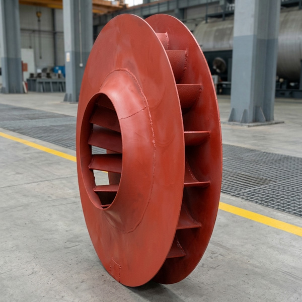
An unsealed outlet damper connects the fan interior with the boiler flue gas duct. When an adjacent boiler adjusts its load, the fan interior can experience negative or positive pressure surges. This pressure fluctuation may cause the fractured link rod end to shift, potentially colliding with the impeller (HU25040-22G-08), and can also cause misalignment when disassembling or assembling the blade bolts (DYL2420-50).
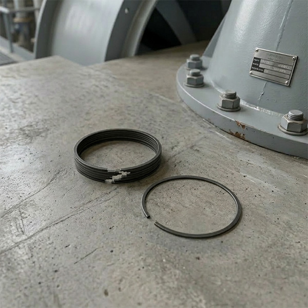
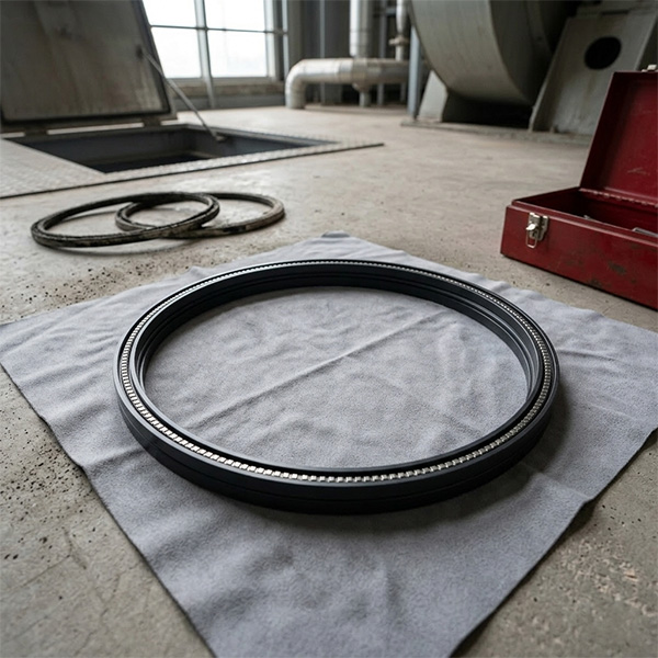
By reinforcing the seal with the CPMW Seal Ring TY9117C UZ22000 (DY) Series T17. This stabilizes the position of the fractured link rod end, allowing for precise operation when removing the old rod or installing the new DTYD100UI002 link rod, thereby preventing bolt installation deviations.
4. Debris Isolation: Extending Complementary Component Life
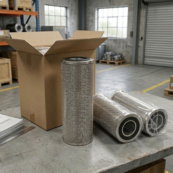
Backflowing flue gas carries fly ash and coal dust. If these particulates adhere to the clevis pin bearing (e.g., Bearing DJJQ40 W5 U236D00 (DY)) or the scraper ring (I UZ22000 (DY)) near the fractured link rod end, it can cause the bearing to seize. When the new DTYD100UI002 link rod is installed, a seized bearing increases transmission resistance, shortening the lifespan of both the link rod and the bearing. Sealing followed by cleaning the fan interior prevents this issue, ensuring the transmission resistance of the DTYD100UI002 link rod remains within the standard range and extending the durability of complementary parts like the scraper ring and bearings.
Practical Tip for Sealing Implementation
Action Key: When sealing, first secure the outlet damper. Use a chain hoist to firmly fix the damper door, then apply the CPMW Laminated Seal U184011 UZ22000 (DY) Series T10 along the edge, followed by reinforcement with a #10 round steel bar. This method is significantly more secure than relying solely on asbestos rope and prevents the seal from falling off during maintenance.
Before replacing the DTYD100UI002 link rod, always confirm the sealing integrity. Then, proceed to align the new link rod with the 01 Model Coupling 5001.1 U238\2ZT (DY) connection, ensuring compliance with the DL/T 468-2019 requirement of “adjustment mechanism transmission accuracy 1%”. This is essential for long-term, trouble-free fan operation.
In summary: Sealing the ID fan outlet damper is not an optional step; it is the safety baseline for link rod fracture maintenance. Choosing a wear-resistant and highly adaptable link rod like the DTYD100UI002, paired with quality components like CPMW seals and blade bolts, allows you to meet safety standards while ensuring the long-term stability of the ID fan's adjustment system—the right path for efficient and worry-free power plant maintenance.
HKZX-2025-10-24


-
Looking at Abnormal Wear on U250-Y01 Induced Draft Fan Moving Blades
Understand why U250-Y01 induced draft fan blades wear out and how to maintain mechanical linkages. We provide U250-Y01 blades, seals, and connecting rods.03-23
-
Easy Maintenance with the SDGLQ-60T-36K Duplex Oil Filter for Coal Mills
Learn how to switch the SDGLQ-60T-36K duplex filter element without stopping your coal mill. No oil flow interruption, stable pressure, and zero bypass. Get a quote today.03-17
-
Keeping Your ID Fan Safe with the U2616G2106Y01 Blade Seal Ring
Protect your HU25042-221G fan with the U2616G2106Y01 blade seal ring. Learn how multi-stage sealing prevents bearing jams, blade sticking, and fan stalls.03-12
-
Stopping Oil Leaks with the UYG35/20G010 ID Fan Seal Ring
Stop bearing box leaks with the UYG35/20G010 ID fan seal ring. Learn how gap control and thermal expansion prevent grip failure in induced draft fan spare parts.03-11
-
How to Detect Micro Leakage in Feed Water Pump Gasket FA1D56-03-09 Before It Causes Shutdown
Learn the common failure modes of feed water pump cooling water jacket sealing gasket FA1D56-03-09, including aging, creep relaxation, and mechanical damage. Understand external signs, micro leakage detection methods, and practical maintenance tips to prevent pump shutdown and reduce repair cost.03-02


