


Enhanced Durability and Efficiency: HU25042-221G Induced Draft Fan Blades for High Back Pressure Flue Gas Systems
Enhanced Durability and Efficiency: HU25042-221G Induced Draft Fan Blades for High Back Pressure Flue Gas Systems
The Challenge: Managing High Back Pressure without Booster Fans
In the current trend of energy conservation and consumption reduction in thermal power units, an increasing number of power plants are opting to eliminate the sulfur dioxide removal (FGD) system booster fan. This transfers the entire flue gas system pressure drop burden onto the Induced Draft (ID) fan. While this design simplifies the system and lowers initial investment costs, it places extremely high demands on the ID fan, particularly its variable pitch control system.
Taking a 330MW unit at a State Power combined heat and power company as an example, its FGD system uses a limestone-gypsum wet process without a booster fan. The ID fan must overcome an additional resistance of approximately 800 to 1200 Pa from the absorber tower, demister, and ductwork.
This demanding condition requires the ID fan to not only maintain sufficient pressure at high loads but also precisely regulate airflow at medium and low loads, avoiding frequent and large-scale adjustments of the variable pitch blades. Prolonged operation under these conditions significantly increases the alternating stress on the blades, compresses the adjustment range, and often leads to reduced efficiency, excessive vibration, and even fatigue cracking of the blades.
Safety and Compliance Concerns
According to the JB/T 8689-2014 Standard for Vibration Limits of Ventilators, if the blade strength or aerodynamic design is insufficient under such operating conditions, it is highly likely to exceed the Class C limit, threatening equipment safety. Furthermore, frequent adjustments impose severe strains on blade seals, bearings, and the actuating mechanism.
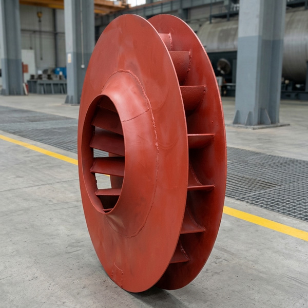
The Solution: HU25042-221G High-Performance ID Fan Blades
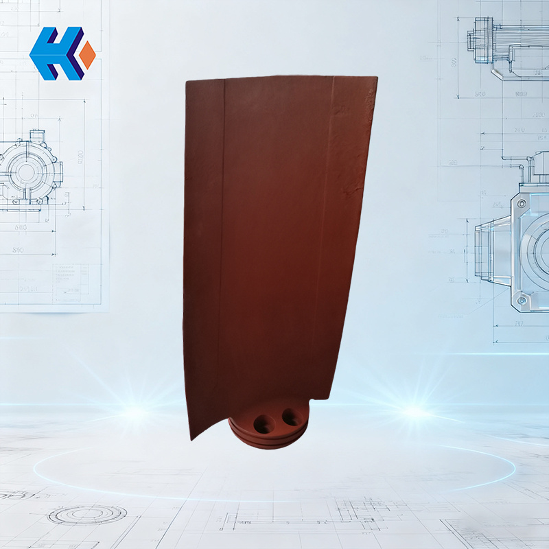
The HU25042-221G ID fan blade (Model: U2616G2106Y00) is specifically engineered for high back pressure and wide adjustment range operation.
- Superior Material & Surface Treatment: The blade utilizes high-strength Q345D steel coupled with a surface strengthening treatment. It is sandblasted and derusted according to the GB/T 8923.1-2011 standard, resulting in strong coating adhesion and excellent corrosion resistance.
- Optimized Aerodynamic Design: The blade’s aerodynamic profile has been optimized through CFD (Computational Fluid Dynamics) analysis. It maintains a wide high-efficiency zone and large stall margin across an adjustment range of -36° to +20°, effectively managing pressure drop fluctuations from the FGD system.
Comprehensive Supporting Components for System Reliability
We provide a complete set of supporting components to ensure reliable system synergy:
|
Component Category |
Part Number(s) |
Key Feature |
|
Sealing |
O-ring Seal (HU25240-22) & Hub O-ring Seal (DTSD60LG016) |
Dual sealing mechanism to prevent flue gas leakage. |
|
Bearing & Shaft |
Sliding Bearing (DTYD100UZ024) & Main Shaft (DTYD30UZ001) |
High-load alloy bearing with precision-machined main shaft for minimized vibration. |
|
Fasteners |
ID Fan Blade Bolt (DYL2420-75) & Blade Bolt (DTYD100UG005) |
Ultrasonic testing per GB/T 11345-2013 to eliminate internal defects. |
|
Actuation |
Actuator Link Rod (DTYD30UI001) |
Enhanced rigidity for more precise and responsive control. |
|
Duct Connection |
Expansion Joint Rubber Sheet (6500×180×8) |
Temperature and corrosion-resistant, absorbs thermal displacement, protects the fan body. |
Proven Performance and Economic Benefits
Practical application in similar power plant retrofit projects confirms the advantages of the HU25042-221G blade:
- The ID fan maintains ample adjustment margin even at the high load of 275MW.
- Efficiency increased by over 6%.
- Annual power savings exceeding 2.4 million kWh.
Conclusion: Eliminating the FGD booster fan poses a "stress test" for the ID fan's variable pitch system. Choosing the HU25042-221G high-performance blade and its complete component set is a fundamentally sound decision to enhance system reliability and economic efficiency.
HKZX-2025-10-24


-
Looking at Abnormal Wear on U250-Y01 Induced Draft Fan Moving Blades
Understand why U250-Y01 induced draft fan blades wear out and how to maintain mechanical linkages. We provide U250-Y01 blades, seals, and connecting rods.03-23
-
Easy Maintenance with the SDGLQ-60T-36K Duplex Oil Filter for Coal Mills
Learn how to switch the SDGLQ-60T-36K duplex filter element without stopping your coal mill. No oil flow interruption, stable pressure, and zero bypass. Get a quote today.03-17
-
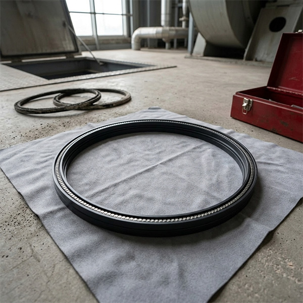
Keeping Your ID Fan Safe with the U2616G2106Y01 Blade Seal Ring
Protect your HU25042-221G fan with the U2616G2106Y01 blade seal ring. Learn how multi-stage sealing prevents bearing jams, blade sticking, and fan stalls.03-12
-
Stopping Oil Leaks with the UYG35/20G010 ID Fan Seal Ring
Stop bearing box leaks with the UYG35/20G010 ID fan seal ring. Learn how gap control and thermal expansion prevent grip failure in induced draft fan spare parts.03-11
-
How to Detect Micro Leakage in Feed Water Pump Gasket FA1D56-03-09 Before It Causes Shutdown
Learn the common failure modes of feed water pump cooling water jacket sealing gasket FA1D56-03-09, including aging, creep relaxation, and mechanical damage. Understand external signs, micro leakage detection methods, and practical maintenance tips to prevent pump shutdown and reduce repair cost.03-02


