


Precision Alignment of Induced Draft Fan Impeller A366Y00: Key to Power Plant Reliability
Precision Alignment of Induced Draft Fan Impeller A366Y00: Key to Power Plant Reliability
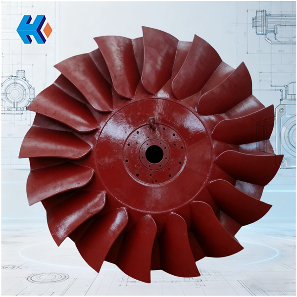
In the overhaul of power plant induced draft (ID) fans, precise impeller alignment is the core factor determining equipment operational stability. Specifically, when installing the impeller onto the main shaft, any inadequacy in controlling the ID fan impeller to main shaft concentricity can lead to minor issues like excessive vibration and premature bearing failure, or severe problems such as blade rubbing, unit trip, and massive economic losses.
Today, leveraging field experience, we discuss how to achieve the precise alignment of the ID Fan Impeller A366Y00 while meeting the stringent vibration requirements of GB/T 10178-2006 (Industrial Ventilators – Performance Testing on Site).
The Standard Requirement for Large Units
For large units,ID fan impellers have large diameters and high operating speeds. The alignment precision between the ID Fan Impeller A366Y00 and the main shaft must be controlled. This demands strict control across the entire process: from fundamental checks to component selection and assembly procedures.
This is the prerequisite for precise impeller alignment:
- Main Shaft Inspection: Before installation, use an inner diameter dial gauge to check the main shaft's taper and use a keyway gauge to check the keyway integrity, ensuring no scoring or corrosion.
- Impeller Hub Preparation: Thoroughly clean the inner wall of the Impeller A366Y00 hub bore, removing any burrs or oil residue. Even minute foreign matter will destroy the fit precision and compromise concentricity.
Component Selection and Concentricity Control
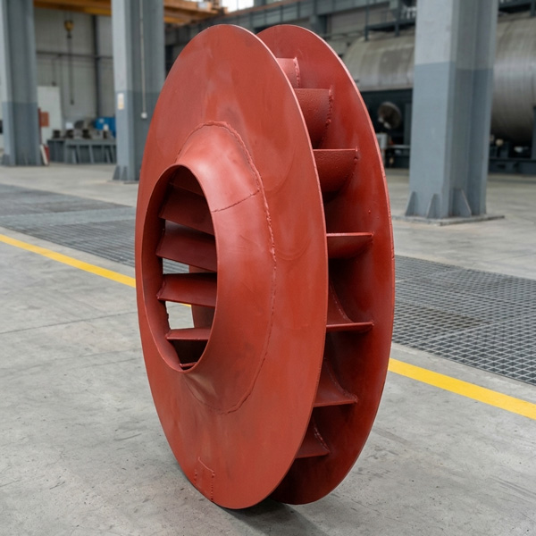
The choice of connection method is critical for controlling ID fan impeller to main shaft concentricity. The mainstream "Tapered Bore + Shaft-End Nut" fitting method utilizes the conical surface for automatic centering, significantly enhancing alignment.
The Impeller A366Y00 features a hub bore processed by high-precision CNC, with the taper tolerance strictly controlled. Furthermore, it is certified under GB/T 25753-2010 (Overspeed Test for Industrial Fan Impellers), ensuring structural stability and excellent dynamic balance performance even at high speeds. This high-precision component quality fundamentally guarantees precise impeller alignment.
During assembly, specialized components and tools are essential to enhance alignment accuracy:
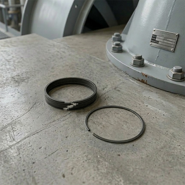
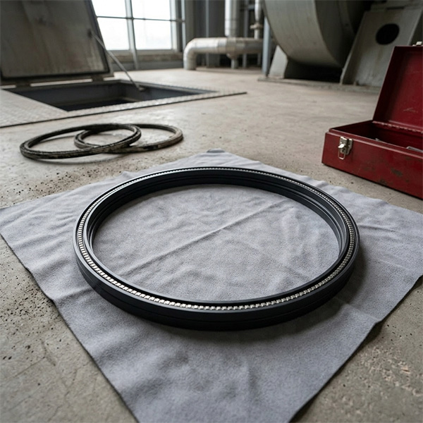
- Axial Positioning: After sliding the Impeller A366Y00 onto the main shaft, first install the Spacer Ring UZ22015. This component precisely positions the impeller axially, preventing axial drift that could compromise concentricity.
- Interference Fit: Use a specialized hydraulic tool to tighten the shaft-end nut evenly, achieving the necessary interference fit. Absolutely avoid hammer installation, which will destroy the taper surface precision and lead to ID fan impeller to main shaft concentricity deviation.
- Overall Alignment: After installing the impeller, the entire assembly must be aligned with the motor/drive system via the coupling. Components like the Elastic Pin Coupling YI35556 and the Type 01 Coupling 5001.1 U238\2ZT (DY) are crucial here. Their excellent error compensation capability can absorb minor deviations. Laser alignment tools must be used to ensure both radial and axial deviations meet the precise ID fan impeller alignment standards.
Systemic Support for Alignment Stability
Sealing and lubrication systems also indirectly affect the alignment stability of the Impeller A366Y00:
- Sealing: An O-Ring W15,D60X2.65,AN33 (19) TU790100SMZY with high-temperature and anti-aging properties must be installed between the main shaft and the bearing housing to prevent flue gas corrosion from degrading the precision fit.
- Lubrication: The Gear Pump F520202000158NB4-D5 must be activated to ensure a smooth oil circuit, reducing rotational resistance.
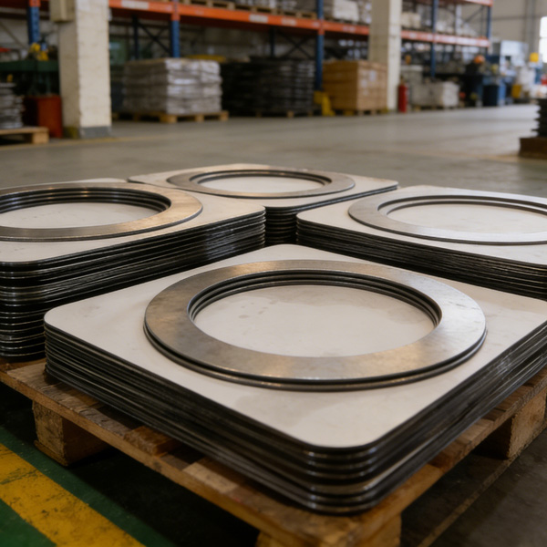
- Other Critical Components: Ensure the Inlet Gasket A350P11 is perfectly sealed, and the Ear Plate A350Z01 and Slider LG232213A are correctly installed. These parts collectively form the systemic guarantee for precise ID fan impeller alignment.
HKZX-2025-10-28


-
Looking at Abnormal Wear on U250-Y01 Induced Draft Fan Moving Blades
Understand why U250-Y01 induced draft fan blades wear out and how to maintain mechanical linkages. We provide U250-Y01 blades, seals, and connecting rods.03-23
-
Easy Maintenance with the SDGLQ-60T-36K Duplex Oil Filter for Coal Mills
Learn how to switch the SDGLQ-60T-36K duplex filter element without stopping your coal mill. No oil flow interruption, stable pressure, and zero bypass. Get a quote today.03-17
-
Keeping Your ID Fan Safe with the U2616G2106Y01 Blade Seal Ring
Protect your HU25042-221G fan with the U2616G2106Y01 blade seal ring. Learn how multi-stage sealing prevents bearing jams, blade sticking, and fan stalls.03-12
-
Stopping Oil Leaks with the UYG35/20G010 ID Fan Seal Ring
Stop bearing box leaks with the UYG35/20G010 ID fan seal ring. Learn how gap control and thermal expansion prevent grip failure in induced draft fan spare parts.03-11
-
How to Detect Micro Leakage in Feed Water Pump Gasket FA1D56-03-09 Before It Causes Shutdown
Learn the common failure modes of feed water pump cooling water jacket sealing gasket FA1D56-03-09, including aging, creep relaxation, and mechanical damage. Understand external signs, micro leakage detection methods, and practical maintenance tips to prevent pump shutdown and reduce repair cost.03-02


