


Mechanical Seal Cooling Jacket Cover HZB253-640-01-12: Key Bolting Techniques for Reliability
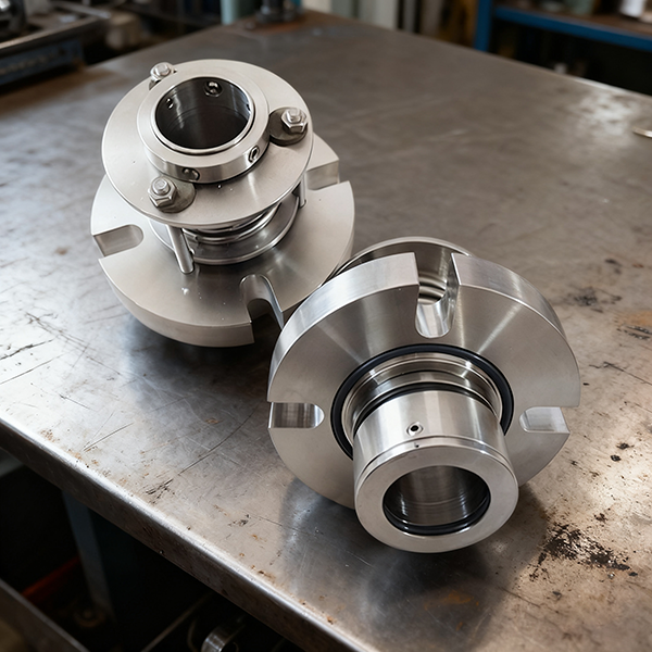
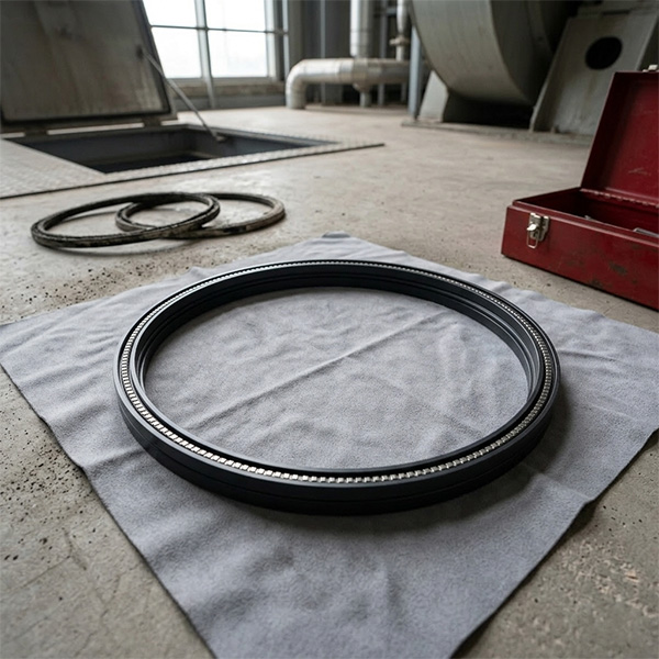
In the demanding feed water systems of thermal power plants, the reliable operation of the HZB253-640 booster pump is fundamental to main unit safety. The Mechanical Seal Cooling Jacket Cover HZB253-640-01-12 is a critical component of the mechanical seal cooling system. Its installation quality, especially the method of bolting, directly impacts sealing performance and equipment longevity. Many site engineers report that minor seepage or cover deformation after installation is often traced back to the seemingly simple step of tightening the bolts. We will now discuss the essential principles for correct fastening.
The cooling jacket cover is secured to the main body of the mechanical seal cooling jacket using socket head cap screws. A rubber asbestos gasket must be placed between the two parts. The core principle here is mandatory: you must use a Symmetrical, Step-by-Step, and Uniform tightening sequence.
Recommended Tightening Procedure for HZB253-640-01-12
Following this precise method prevents component stress and ensures a perfect seal:
- Pre-tightening Phase: Start by using hand tools or a low-torque wrench to initially snug all screws. This ensures the gasket sits flat against the mating surface without any warping or curling.
- Step-by-Step Tightening: Using a torque wrench, apply force gradually in 2 to 3 increments following a diagonal pattern (e.g., 12 o'clock → 6 o'clock → 3 o'clock → 9 o'clock). Each step should increase the torque by approximately one-third of the final target value.
- Final Torque and Verification: Once the specified final torque value is reached, perform a final check following the same diagonal sequence. This confirms that the force distribution across the entire cover is balanced and uniform.
Why Symmetrical Tightening is Essential
The cooling jacket cover is typically made of cast iron or cast steel, materials that possess good rigidity but are inherently brittle. If one side or one screw is tightened fully first, it causes localized stress and deformation in the cover plate. This results in an uneven mating surface, leading to leakage even if the gasket is new, due to non-uniform contact stress. More critically, a deformed cover plate can disrupt the axial positioning of the internal mechanical seal, causing uneven wear on the seal faces or even catastrophic overheating failure.
Two Critical Installation Details
Beyond the tightening sequence, you must pay attention to two vital details:
- Gasket and O-ring Replacement: Always install new gaskets and O-rings during every major overhaul. Used gaskets lose elasticity and cannot reliably form a tight seal, regardless of how much force is applied.
- Surface Preparation: Thoroughly clean the mating surfaces before installation. All traces of rust, oil film, or burrs must be removed, as these contaminants are essentially time bombs placed on the sealing surface.
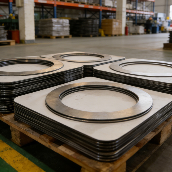
As a specialist in power auxiliary equipment spares for over ten years, Huakaishengrui provides the Mechanical Seal Cooling Jacket Cover HZB253-640-01-12 manufactured strictly according to original drawings. Made from HT250 high-strength gray cast iron, the sealing face is precision-ground to a flatness of ≤ 0.05mm, fully meeting the stringent sealing requirements of the power plant environment. When paired with this correct fastening procedure, it effectively eliminates cooling water leakage and ensures the long-term stable operation of the mechanical seal.
Remember the rule: Three slow turns of the wrench save three days of emergency repairs. In the high-temperature, high-pressure environment of a power station, details determine success.
Full Range of booster pump Spares for One-Time Overhaul
In addition to this core component, we also supply the complete range of sealing and shaft system spares for the HZB253-640 booster pump, ensuring your overhaul is right the first time:
| Component Name | Model | Application |
|---|---|---|
| Shaft Sleeve | HZB253-640-01-04 | Shaft protection |
| booster pump O-ring | HZB253-640-03-09 | Static seal auxiliary |
| Gasket | HZB253-640-03-06 | Sealing between casings |
| Cooling Water Chamber Gasket | HZB253-640-03-07 | Water chamber sealing |
| Oil Slinger Ring | HZB253-640-01-05 | Bearing protection |
| Shaft Sleeve | HZB253-640-01-06 | Shaft protection and wear surface |
| O-ring | HZB253-640-03-08 | Static seal auxiliary |
| O-type Rubber Seal Ring | HZB253-640-02-01 | Primary rubber seal |
| Stop Washer | HZB253-640-01-14 | Axial positioning |
| Shaft Sleeve (Drive End) | HZB253-640-01-10 | Drive end shaft protection |
Contact us for genuine parts and expert advice to simplify your booster pump maintenance and guarantee equipment safety.
HKCYT-2025-12-03


-
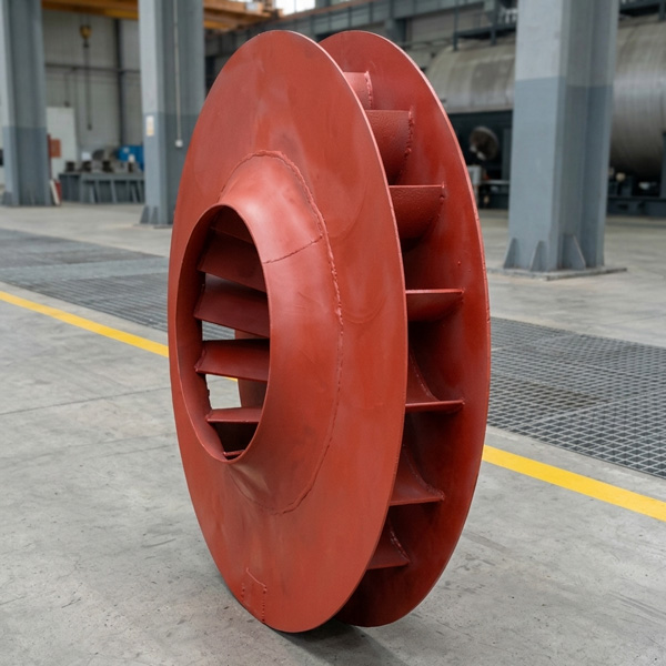
Looking at Abnormal Wear on U250-Y01 Induced Draft Fan Moving Blades
Understand why U250-Y01 induced draft fan blades wear out and how to maintain mechanical linkages. We provide U250-Y01 blades, seals, and connecting rods.03-23
-
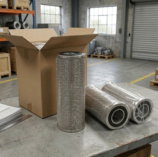
Easy Maintenance with the SDGLQ-60T-36K Duplex Oil Filter for Coal Mills
Learn how to switch the SDGLQ-60T-36K duplex filter element without stopping your coal mill. No oil flow interruption, stable pressure, and zero bypass. Get a quote today.03-17
-
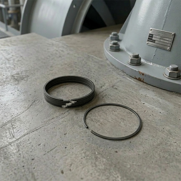
Keeping Your ID Fan Safe with the U2616G2106Y01 Blade Seal Ring
Protect your HU25042-221G fan with the U2616G2106Y01 blade seal ring. Learn how multi-stage sealing prevents bearing jams, blade sticking, and fan stalls.03-12
-
Stopping Oil Leaks with the UYG35/20G010 ID Fan Seal Ring
Stop bearing box leaks with the UYG35/20G010 ID fan seal ring. Learn how gap control and thermal expansion prevent grip failure in induced draft fan spare parts.03-11
-
How to Detect Micro Leakage in Feed Water Pump Gasket FA1D56-03-09 Before It Causes Shutdown
Learn the common failure modes of feed water pump cooling water jacket sealing gasket FA1D56-03-09, including aging, creep relaxation, and mechanical damage. Understand external signs, micro leakage detection methods, and practical maintenance tips to prevent pump shutdown and reduce repair cost.03-02


