


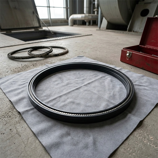
Troubleshooting and Installing the DTPD100UZ002 Induced Draft Fan Bearing Housing
One of the most persistent headaches during the overhaul of an induced draft (ID) fan is the improper installation of the main bearing housing. This often leads to misalignment, excessive vibration after tightening, and, in severe cases, the impeller rubbing against the casing. The root cause usually lies in one of two areas: the fan casing and the bearing housing were not mounted precisely, or the concentricity was not properly adjusted.
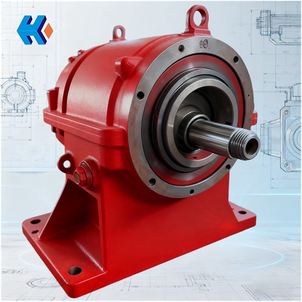
Using the DTPD100UZ002 bearing housing as our example, let's detail how to securely mount it to the fan casing while ensuring the main shaft runs smoothly and stably.
1. Positioning: The Guiding Role of the Casing's Shoulders
This ID fan utilizes a horizontally split casing structure. The lower half of the casing is equipped with a locating shoulder (止口/jizhima) specifically designed to receive the bearing housing.
-
The DTPD100UZ002 housing has a matching locating boss on its bottom surface.
-
The fitting clearance between the shoulder and the boss is tightly controlled at 0.02 to 0.03 mm.
-
Significance: By simply placing the housing gently into the shoulder, the lateral (horizontal) position is inherently corrected. This eliminates the need for repeated manual measurements, making the process both faster and more accurate.
*
2. Fastening: Precision Tightening Sequence
The housing flange has eight highly precise bolt holes (H7 tolerance class), perfectly suited for high-strength bolts.
-
Crucial Tip: The Three-Step Diagonal Tightening
-
Do not rush the tightening process. It must be performed diagonally and in three stages to prevent housing deformation under stress.
-
First Pass: 50% of the final torque.
-
Second Pass: 80% of the final torque.
-
Final Pass: 100% of the final torque (typically 80–100 N·m, depending on bolt specifications).
-
-
-
This method is not just a best practice; it is explicitly required by standards like GB/T 1236-2017 to ensure a rigid and non-deformed installation.
3. The Key to Success: Achieving Concentricity
True stability depends on achieving proper concentricity between the bearing housing and the fan's rotational centerline. The DTPD100UZ002 design achieves this through two main features:
-
Precision Machining: The inner bore of the bearing seat and the bottom locating boss are machined simultaneously using CNC equipment. This process guarantees a coaxiality error of no more than $0.02 \text{ mm}$.
-
Self-Correction: The fan casing's locating shoulder guides the entire bearing housing, causing it to automatically "self-align" to the fan's central axis.
4. Verification and Adjustment
How do you verify that the installation is successful?
-
Procedure: Mount a dial indicator on the fan casing, position the stylus against the inner bore of the bearing seat, and slowly rotate (bar) the main shaft.
-
Acceptance Criteria: If the radial runout is 0.01 mm, the alignment is satisfactory.
-
Adjustment: If the runout exceeds the tolerance, slightly loosen or tighten a few of the flange bolts. This allows for small, controlled "micro-adjustments" to nudge the housing back into perfect alignment.
5. Associated Components
The bearing housing is only one part of a robust assembly. Field work often involves the following associated parts:
-
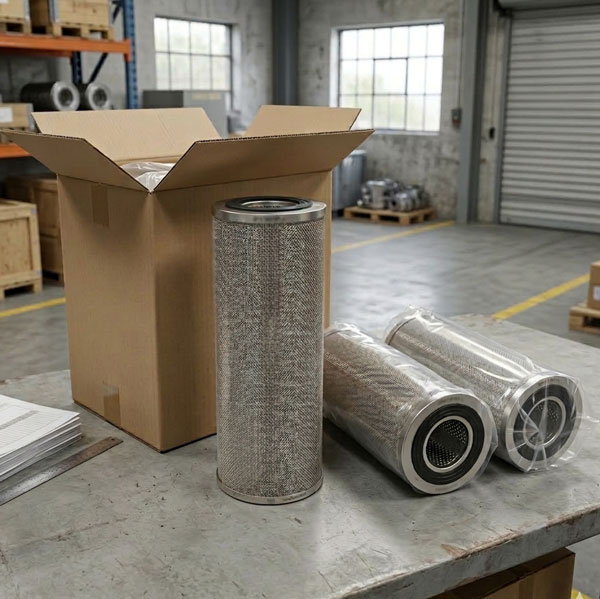
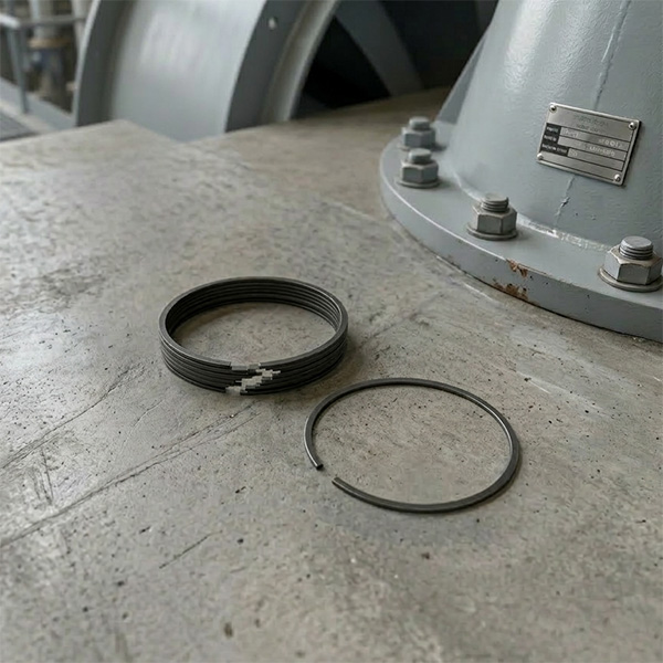
Seals: CPMW laminated seal U184011 UZ22000 and seal ring HU25244-12G are used to prevent flue gas from entering the bearing box.
-
Bearings/Bushings: Spherical plain bearing GE17, FAG radial bearing, and composite bushing ⅢDTYD30LG023 ensure the main shaft rotates flexibly.
-
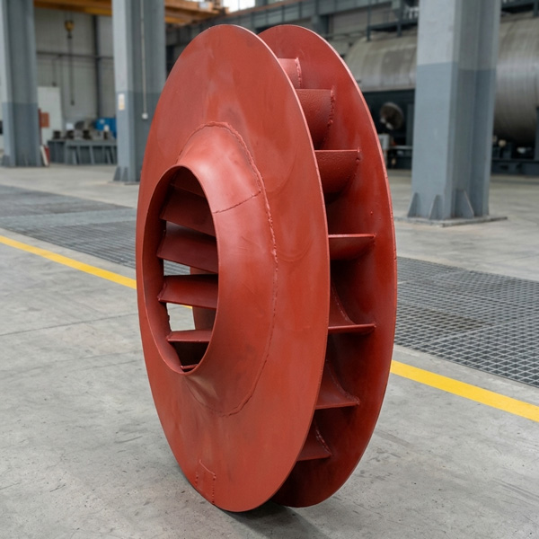
Tools: The YKS1120-10TH specialized puller is essential for safely removing old impellers without damaging the shaft.
-
Other Parts: Components such as the intermediate shaft, crank, impeller shroud, and end caps are all designed as a matched set, and must be installed together for overall stability.
Final Reminder
If you consistently struggle to achieve the correct concentricity, first check the locating shoulder and boss for any nicks, dents,
or accumulated dust/debris. If the fit is found to be loose, you may need to replace the seals and re-calibrate the entire assembly.
HKZX-2025-12-16


-
Looking at Abnormal Wear on U250-Y01 Induced Draft Fan Moving Blades
Understand why U250-Y01 induced draft fan blades wear out and how to maintain mechanical linkages. We provide U250-Y01 blades, seals, and connecting rods.03-23
-
Easy Maintenance with the SDGLQ-60T-36K Duplex Oil Filter for Coal Mills
Learn how to switch the SDGLQ-60T-36K duplex filter element without stopping your coal mill. No oil flow interruption, stable pressure, and zero bypass. Get a quote today.03-17
-
Keeping Your ID Fan Safe with the U2616G2106Y01 Blade Seal Ring
Protect your HU25042-221G fan with the U2616G2106Y01 blade seal ring. Learn how multi-stage sealing prevents bearing jams, blade sticking, and fan stalls.03-12
-
Stopping Oil Leaks with the UYG35/20G010 ID Fan Seal Ring
Stop bearing box leaks with the UYG35/20G010 ID fan seal ring. Learn how gap control and thermal expansion prevent grip failure in induced draft fan spare parts.03-11
-
How to Detect Micro Leakage in Feed Water Pump Gasket FA1D56-03-09 Before It Causes Shutdown
Learn the common failure modes of feed water pump cooling water jacket sealing gasket FA1D56-03-09, including aging, creep relaxation, and mechanical damage. Understand external signs, micro leakage detection methods, and practical maintenance tips to prevent pump shutdown and reduce repair cost.03-02


