


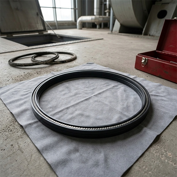
Installation Specifications for Servo Valve Gasket TY9100B.1
1. Pre-installation Preparation
Preparation is the foundation of a successful seal.
-
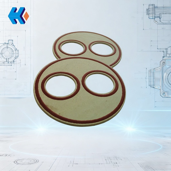
Component Selection: Ensure the use of the TY9100B.1 gasket, specifically designed for adjustable axial fans. This model features oil-resistant, high-performance sealing materials optimized for servo valve environments.
-
Tooling & Hygiene: Prepare clean, specialized tools, lint-free cloths, and a lubricant/grease compatible with the system’s hydraulic oil.
-
PPE: Use protective gloves and standard safety gear to prevent manual contamination of the hydraulic interface.
2. Shutdown, Depressurization, and Site Cleaning
-
Power Down: Deactivate the power source for both the fan and the hydraulic system to ensure the equipment is at a complete standstill.
-
Isolation: Close the upstream and downstream isolation valves to cut off the flow of hydraulic oil.
-
Pressure Relief: Slowly open the bleed valve to release residual pressure within the pipelines and the servo valve body. This prevents accidental oil spray during disassembly.
-
Environmental Control: Clean the installation area of all dust, grease, and debris. A pristine environment is critical to prevent "silent killers" (micro-particles) from entering the precision internals of the servo valve.
3. Key Installation Procedures
Strict adherence to these steps is mandatory:
-
Step 1: Surface Preparation. After removing the old gasket, use a lint-free cloth to wipe the mounting seat and sealing cavity. Surfaces must be free of impurities, oil, scratches, or corrosion. If minor damage is found on the sealing surface, use fine-grit sandpaper to lightly buff it flat.
-
Step 2: Gasket Inspection & Lubrication. Inspect the new TY9100B.1 gasket for cracks, deformation, or manufacturing defects. Apply a thin, uniform layer of compatible grease to the sealing surface. Caution: Do not over-apply grease, as excess lubricant can contaminate the hydraulic fluid.
-
Step 3: Precise Positioning. Place the gasket steadily into the mounting groove. Ensure it is perfectly flush and centered. Misalignment or skewing will inevitably lead to sealing gaps and premature failure.
-
Step 4: Torque-Controlled Fastening. Use a torque wrench to tighten the mounting bolts or end caps to the specified values.
-
Avoid Over-tightening: This can deform the gasket or crack the servo valve housing.
-
Avoid Under-tightening: This results in an insufficient seal.
-
4. Post-Installation Inspection and Commissioning
-
Static Leak Test: Close the bleed valve and slowly open the isolation valves. Observe the gasket interface for any signs of seepage.
-
Dynamic Monitoring: Start the hydraulic system and fan. Monitor the servo valve’s pressure and flow parameters for stability. Listen for abnormal noise and watch for leaks during operation.
-
Corrective Action: If a leak is detected, immediately shut down and depressurize the system. Re-inspect the seating of the gasket and the integrity of the sealing surface before re-testing.
| Component Name | Model / Part Number | Primary Application / Description |
| Half-Coupling (Motor Side) | 3201.1 U150\3ZT | Connects the motor to the drive shaft to transmit torque. |
| Washer/Gasket | W19, AN33(19), TU790100SMZY | Provides axial sealing and buffered support. |
| Rolling Bearing | U236D03 / U236D00(DY) | Supports the rotor and reduces rotational friction. |
| Connecting Pin | TY900106 | Secures the crank and linkage mechanism. |
| Crank | LG232208A | Converts servo valve movement into blade pitch adjustment. |
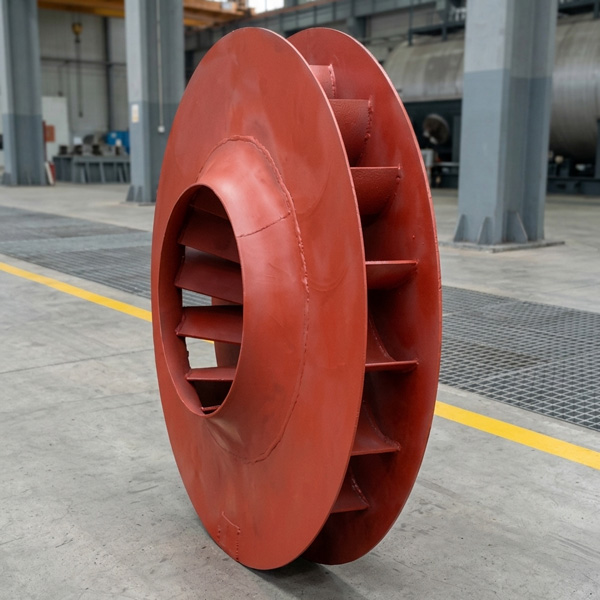
| Impeller Assembly | A266D00-SKA | The core functional component of the fan; facilitates airflow transport and pressurization. |
| Cooling & Sealing Fan Assembly | YKS1120-10TH | Provides cooling and positive pressure dustproofing for bearings and seals. |
| Shaft Sleeve | TU790101 | Protects the shaft surface; facilitates easy disassembly and replacement of wear parts. |
| Combined Seal Ring | U2515G2106Y010 | Features a multi-layered sealing structure to prevent lubricating oil leakage. |
| Motor-side Coupling | DTYD30FM002 | High-precision connection for the motor output shaft. |
| Hub Disc | DTYD100LG004 | Houses the blades and transmits adjustment torque. |
HKZX-2025-12-17


-
Looking at Abnormal Wear on U250-Y01 Induced Draft Fan Moving Blades
Understand why U250-Y01 induced draft fan blades wear out and how to maintain mechanical linkages. We provide U250-Y01 blades, seals, and connecting rods.03-23
-
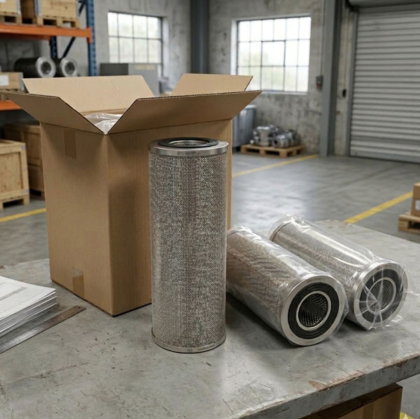
Easy Maintenance with the SDGLQ-60T-36K Duplex Oil Filter for Coal Mills
Learn how to switch the SDGLQ-60T-36K duplex filter element without stopping your coal mill. No oil flow interruption, stable pressure, and zero bypass. Get a quote today.03-17
-
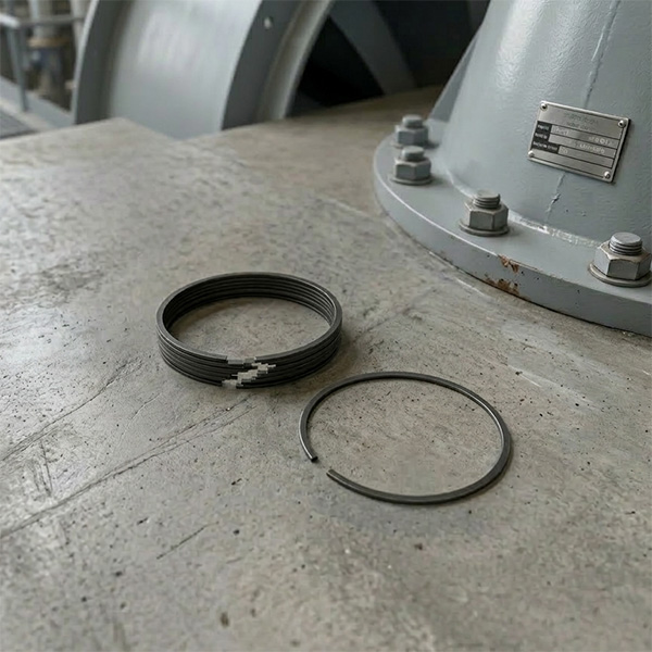
Keeping Your ID Fan Safe with the U2616G2106Y01 Blade Seal Ring
Protect your HU25042-221G fan with the U2616G2106Y01 blade seal ring. Learn how multi-stage sealing prevents bearing jams, blade sticking, and fan stalls.03-12
-
Stopping Oil Leaks with the UYG35/20G010 ID Fan Seal Ring
Stop bearing box leaks with the UYG35/20G010 ID fan seal ring. Learn how gap control and thermal expansion prevent grip failure in induced draft fan spare parts.03-11
-
How to Detect Micro Leakage in Feed Water Pump Gasket FA1D56-03-09 Before It Causes Shutdown
Learn the common failure modes of feed water pump cooling water jacket sealing gasket FA1D56-03-09, including aging, creep relaxation, and mechanical damage. Understand external signs, micro leakage detection methods, and practical maintenance tips to prevent pump shutdown and reduce repair cost.03-02


