


Practical Guide: HZB253-640-03-10 Cooling Sleeve Assembly & Sealing Pitfalls
In 300MW to 600MW thermal power units, the booster pump is the vanguard for the feed water system. If it fails, the safety of the entire main unit is at risk. The HZB253-640-03-10 mechanical seal cooling sleeve is the critical backbone of that pump's sealing system. If the assembly is off, you are looking at anything from a prematurely trashed mechanical seal to cooling water leaks or medium overflow—eventually forcing an unplanned shutdown.
After over a decade in power plant auxiliary maintenance, I have seen too many people fall into the same traps due to improper cooling sleeve installation. Today, I am breaking down the correct assembly sequence and critical sealing requirements for the HZB253-640-03-10. Pair these steps with high-quality spares, and you will finally achieve zero-leak, long-cycle operation.
I. Core Assembly Principle: Inside-Out, Fix First, Connect Last
Do not just wing the assembly order. Follow the core principle of Inside-Out, Fix First, Connect Last. One mistake here can force a total teardown and restart. Here is the step-by-step breakdown:
Step 1: Pre-install the Sleeve Body—New Gaskets are Mandatory
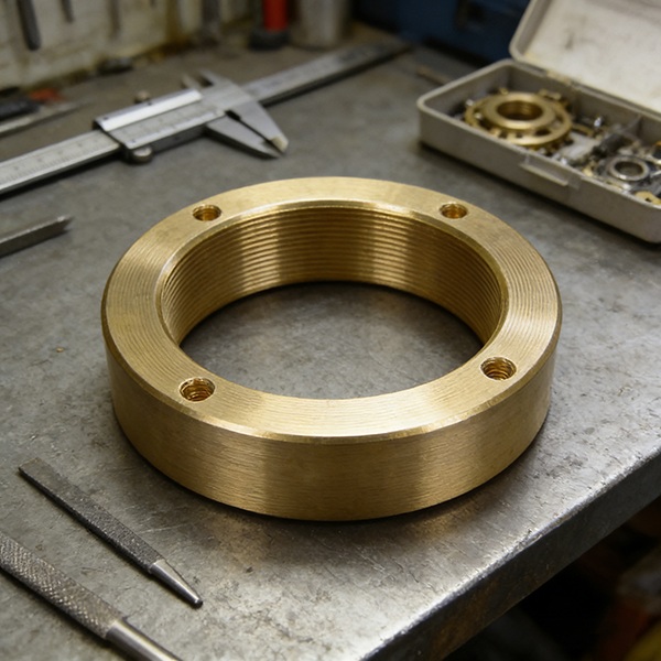
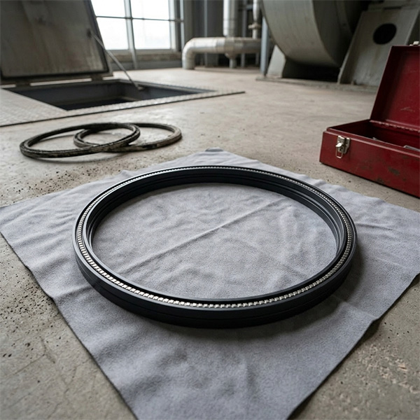
Align the HZB253-640-03-10 cooling sleeve (manufactured by Dongfang SRI) with the corresponding mounting position on the pump end cover. Use internal hex socket head screws for initial fixing. The golden rule here: The rubber-asbestos gasket between the pump cover and the cooling sleeve must be replaced with a brand-new one! Even if the old one looks fine, it has likely lost its elasticity. Once the gasket is laid flat and centered, tighten the fixing screws evenly.
Step 2: Install the Cooling Sleeve Cover—Cleanliness is Everything
Next, mount the cover onto the cooling sleeve, again using a new gasket. The most ignored part here is the mating surface cleanliness. You must wipe the surfaces between the sleeve and the cover until they are spotless. No scratches, no rust, no grit. Even a single grain of sand can cause a cooling water leak. If that water leaks, you lose control over the seal chamber temperature, and the mechanical seal will fail shortly after. Tighten the screws evenly to ensure a tight fit.
Step 3: Insert the Mechanical Seal—Replace Every O-Ring
Apply a light layer of lubricant to the pump shaft to prevent scratching the seal during installation. Slide the cartridge-style mechanical seal slowly along the shaft until it fits snugly against the end face of the cooling sleeve. Watch out for two things:
- O-Rings: Every single O-ring (on the seal body and bearing end cover) must be brand new. Never reuse them.
- Spacers: Check the three assembly spacers; make sure they are firmly engaged so nothing shifts during the final steps.
Step 4: Fastening and Piping—Symmetry Prevents Loading Bias
Thread the four nuts onto the mechanical seal gland studs just enough to hold them—do not tighten yet. Once the rotor is positioned, tighten the nuts in a symmetrical, diagonal pattern. This prevents loading bias, which causes uneven pressure and leaks. Finally, connect the inlet and outlet water pipes. Run a small amount of water through first to check for clogs or drips before full operation.
II. Critical Sealing Requirements: The Deal-Breakers
Even with perfect assembly, your seal will fail if you miss these three points. These are the pitfalls learned from countless overhauls:
- Disposable Components: All static seals (gaskets, O-rings) are one-time-use items. Aging and deformation are often invisible to the eye but lead to massive leaks later.
- Surface Quality: Check the mating surfaces of the sleeve and pump cover for burrs or corrosion. I recommend applying a tiny amount of silicone sealant to these surfaces to provide an extra layer of defense.
- Water Quality: The cooling water must be clean. Debris in the water will clog the throttle holes in the sleeve, killing the cooling effect. Flush your lines before connecting them.
III. High-Quality Spares + Correct Assembly = Stable Operation
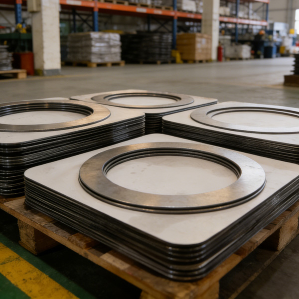
Even the best assembly process cannot save a low-quality part. Dongfang SRI has focused on power plant spares for over a decade. Our HZB253-640-03-10 cooling sleeves are built strictly to original drawings, ensuring material purity and dimensional accuracy that pass the toughest plant inspections.
We provide more than just the sleeve. We offer the full range of HZB booster pump wear parts, preventing the compatibility issues that happen when you mix and match different brands. Here is your core spare parts list:
| Product Name | Model / Spec | Core Purpose |
|---|---|---|
| Booster Pump | HZB253-640 | The main unit ensuring boiler water supply stability. |
| O-Ring | HZB253-640-02-01 | Prevents medium leakage and cooling water ingress. |
| Shaft Sleeve | HZB253-640-01-14 | Protects the pump shaft from friction and wear. |
| Lock Washer | HZB253-640-01-11 | Ensures the shaft sleeve and components don't loosen during vibration. |
| Gasket | HZB253-640-03-24 | The primary static seal for the sleeve and end cover mating surfaces. |
| End Cover | HZB253-640-03-02/05 | Isolates the pump internals from external piping. |
| Pump Casing | HZB253-640-03-03 | The pressure-bearing housing for the booster pump. |
| Main Shaft | HZB253-640 | The core power-transmission component driving the impeller. |
Summary: Keep it Steady
Assembling the HZB253-640-03-10 cooling sleeve is simple if you stick to the Inside-Out rule and get the details right: new gaskets, clean surfaces, and new O-rings. Combine that with Dongfang SRI spares, and you will stop fighting leaks and start running steady.
If you have technical questions during your assembly or need help selecting the right spares for your HZB253-640 pump, reach out to us. Our technical team is ready to help you finish your overhaul efficiently.
HKCYT-2025-12-22


-
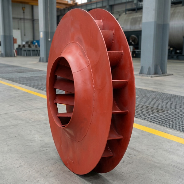
Looking at Abnormal Wear on U250-Y01 Induced Draft Fan Moving Blades
Understand why U250-Y01 induced draft fan blades wear out and how to maintain mechanical linkages. We provide U250-Y01 blades, seals, and connecting rods.03-23
-
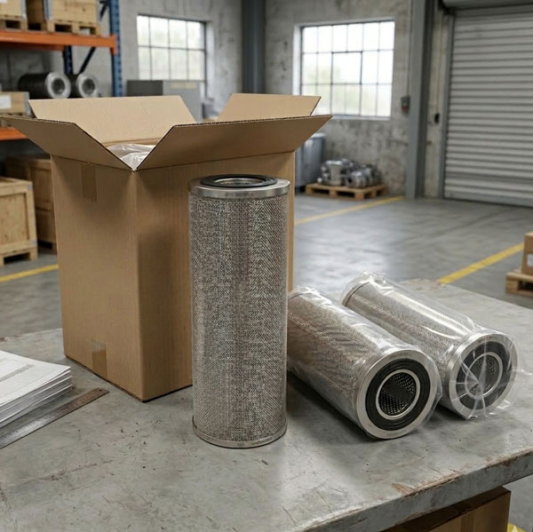
Easy Maintenance with the SDGLQ-60T-36K Duplex Oil Filter for Coal Mills
Learn how to switch the SDGLQ-60T-36K duplex filter element without stopping your coal mill. No oil flow interruption, stable pressure, and zero bypass. Get a quote today.03-17
-
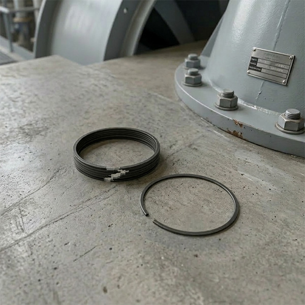
Keeping Your ID Fan Safe with the U2616G2106Y01 Blade Seal Ring
Protect your HU25042-221G fan with the U2616G2106Y01 blade seal ring. Learn how multi-stage sealing prevents bearing jams, blade sticking, and fan stalls.03-12
-
Stopping Oil Leaks with the UYG35/20G010 ID Fan Seal Ring
Stop bearing box leaks with the UYG35/20G010 ID fan seal ring. Learn how gap control and thermal expansion prevent grip failure in induced draft fan spare parts.03-11
-
How to Detect Micro Leakage in Feed Water Pump Gasket FA1D56-03-09 Before It Causes Shutdown
Learn the common failure modes of feed water pump cooling water jacket sealing gasket FA1D56-03-09, including aging, creep relaxation, and mechanical damage. Understand external signs, micro leakage detection methods, and practical maintenance tips to prevent pump shutdown and reduce repair cost.03-02


