


Induced Draft Fan Servo Valve Connecting Rod HU25238-22: Failure Analysis and Mitigation
From Crisis Response to Long-Term Prevention: A Comprehensive Solution to Connecting Rod Fracture
Let's face it: the induced draft (ID) fan's dynamic adjustment connecting rod—let's just call it the link—is a tiny powerhouse. It's the critical transmission component that bridges the hydraulic actuator with the variable pitch vane (or dynamic blade) control system. Its job? To transmit the necessary torque for precise flow regulation. When this small but mighty piece snaps, the result is anything but minor. Vane angle control immediately fails, forcing an emergency fan shutdown, severely compromising the unit's safety and stable operation, and potentially triggering a nasty cascade of equipment failures. You really don't want that.
Root Cause Analysis: Tracing the Breakdown
Connecting rod fractures usually aren't a single-event drama; they're often the culmination of one or more contributing factors. Identifying the "who, what, and why" is the first step to a permanent fix.
1. Fatigue is the Main Culprit
This is the big one. During operation, the link is constantly battered by complex, cyclic stresses and vibrational loads. Over a long service life under these repetitive loads, micro-cracks inevitably form within the material and gradually grow. Eventually, they reach a critical size, leading to catastrophic fatigue fracture. These failures are particularly prone to occurring at stress concentration points—think the root of threads or where the cross-section changes dramatically. It's like a paperclip you bend back and forth too many times.
2. Abnormal Load Shock
Sometimes, the system just gets hit with a massive, unexpected jolt. Events like ID fan stalling or extreme fluctuations in oil pressure can subject the connecting rod to impact loads far exceeding its design capacity. This abnormal loading almost always results in sudden overload fracture.
3. Corrosion and Wear-Induced Weakness
Operating in harsh industrial environments is tough. The link's surface can suffer from corrosion, or its connection points can experience excessive abrasion. Either way, the effective cross-sectional area—and thus the load-bearing capacity—is diminished. Once weakened, the link can fail even under normal operating conditions.
Solutions and Steps: A Systemic Response Strategy
When a fracture occurs, the response must be immediate, methodical, and safe.
A broken dynamic adjustment link mandates an immediate, unplanned shutdown of the ID fan. Since pitch control is lost, the critical next step is closing the ID fan’s inlet electric damper. This is a high-risk maneuver, so watch out for these major pitfalls:
- Preventing Stall and Backdraft: While gradually closing the damper, you must meticulously monitor the fan’s status to prevent it from stalling and to avoid a dangerous draft-fight (or 'robbing') between the two operating ID fans.
- Stabilizing the Hydraulic System: A fan stall can cause massive oil pressure swings, potentially disrupting the balance within the dynamic adjustment servo valve oil chambers, leading to the vanes suddenly snapping shut.
- Controlling Negative Pressure: Keep a hawk-eye on the negative pressure at the ID fan inlet. It absolutely must not exceed the duct's design pressure limit (e.g., -7.176 KPa) to avoid catastrophic flue gas duct damage.
- Avoiding Prolonged Low-Load Operation: Don’t let the ID fan run too long at low output with a very small inlet damper opening, as this is terrible for the equipment.
- Standardizing Isolation Procedures: Stick rigorously to the standard operating procedures when isolating the fan to prevent an avoidable trip.
Once the immediate crisis is managed, the real work of repair begins.
- System Disassembly Check: Thoroughly dismantle and inspect the hydraulic actuator.
- Non-Destructive Testing (NDT): Subject related components to magnetic particle or ultrasonic testing. You need to catch those hidden cracks!
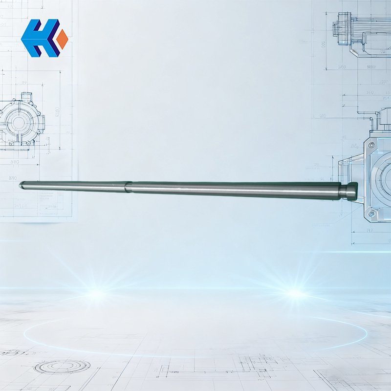
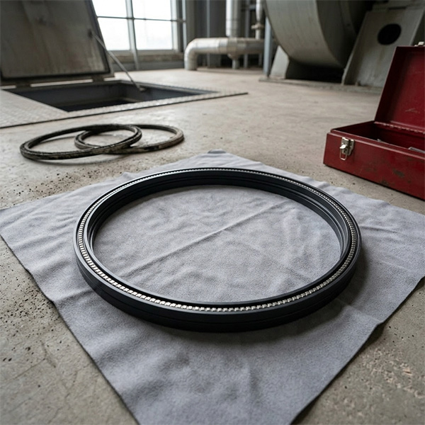
- Damaged Part Replacement: Replace the fractured link and any associated damaged parts. Here, we strongly recommend using the specified Servo Valve Connecting Rod HU25238-22.
Introducing the HU25238-22 Upgrade: Your Fatigue Fix
We strongly endorse the use of our specialized Induced Draft Fan Servo Valve Connecting Rod HU25238-22. We engineered this product specifically to defeat the common failure modes:
- Material Overhaul: It utilizes a high-strength alloy steel, put through a specialized heat treatment process. Result? Fatigue strength is boosted by over 30%.
- Structural Optimization: We've cleverly redesigned the notorious stress concentration areas, significantly extending the service life.
- Precision Guaranteed: Tight, precision machining ensures perfect fit and alignment, which minimizes abnormal wear and tear.
- Reliability: Every batch comes with complete material and heat treatment certifications. No guesswork.
Switching to the HU25238-22 effectively eliminates the problem of uncontrollable dynamic blade angle, ensuring your control system runs reliably—and quietly.
Given that the ID fan is a piece of high-precision kit, a bulletproof maintenance plan is non-negotiable.
- Regular Cleaning: Stay on top of cleaning—sensors, filters, cooling seal fan screens, and overflow pipe grids all need timely attention.
- Fastener Checks: Periodically inspect and tighten all bolts and threaded connections. If it moves, secure it.
- Lubrication Management: A typical schedule involves lubrication inspection six times per month to ensure proper oil application.
- Scheduled Overhauls: Implement both planned and non-planned outages based on the fan's operating cycle for essential maintenance.
Proactive Improvement Measures: Looking Ahead
To truly transition from firefighting to fire prevention, consider these upgrades:
- Monitoring Systems: Install vibration and stress monitoring sensors on key components. Knowledge is power.
- Operational Procedures: Fine-tune the fan start-up and shut-down procedures to minimize the chance of those stress-inducing abnormal conditions.
- Scheduled Component Replacement: Establish a strict, preventive replacement schedule for critical components, including the Servo Valve Connecting Rod HU25238-22. Don't wait for it to break.
- Operator Training: Intensify training for operating staff to sharpen their skills in handling abnormal conditions.


-
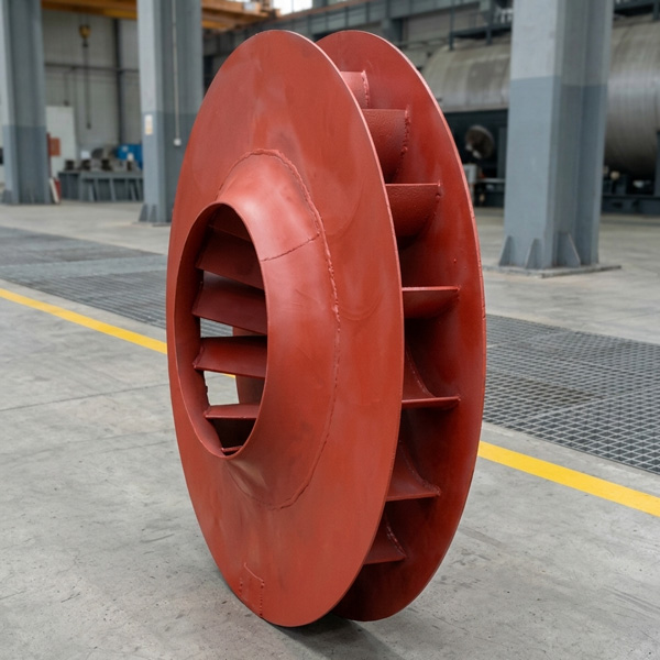
Looking at Abnormal Wear on U250-Y01 Induced Draft Fan Moving Blades
Understand why U250-Y01 induced draft fan blades wear out and how to maintain mechanical linkages. We provide U250-Y01 blades, seals, and connecting rods.03-23
-
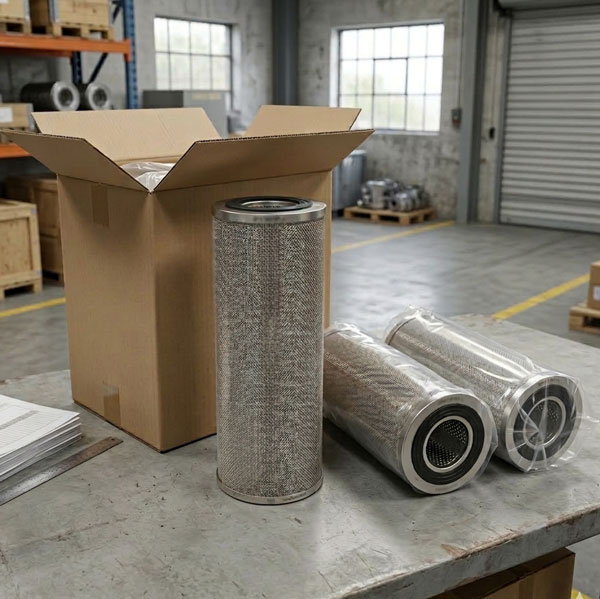
Easy Maintenance with the SDGLQ-60T-36K Duplex Oil Filter for Coal Mills
Learn how to switch the SDGLQ-60T-36K duplex filter element without stopping your coal mill. No oil flow interruption, stable pressure, and zero bypass. Get a quote today.03-17
-
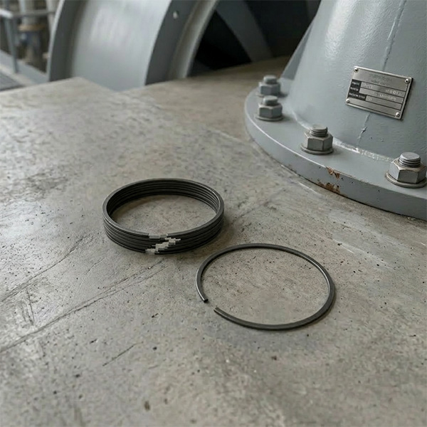
Keeping Your ID Fan Safe with the U2616G2106Y01 Blade Seal Ring
Protect your HU25042-221G fan with the U2616G2106Y01 blade seal ring. Learn how multi-stage sealing prevents bearing jams, blade sticking, and fan stalls.03-12
-
Stopping Oil Leaks with the UYG35/20G010 ID Fan Seal Ring
Stop bearing box leaks with the UYG35/20G010 ID fan seal ring. Learn how gap control and thermal expansion prevent grip failure in induced draft fan spare parts.03-11
-
How to Detect Micro Leakage in Feed Water Pump Gasket FA1D56-03-09 Before It Causes Shutdown
Learn the common failure modes of feed water pump cooling water jacket sealing gasket FA1D56-03-09, including aging, creep relaxation, and mechanical damage. Understand external signs, micro leakage detection methods, and practical maintenance tips to prevent pump shutdown and reduce repair cost.03-02


