


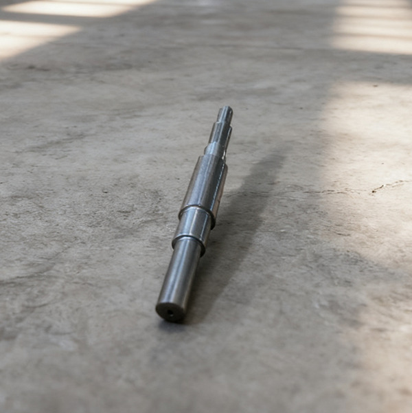
Stopping the Leak: Precision Control for the HZB253-640-01-01 Boiler Feed Pump Shaft
The boiler booster pump shaft HZB253-640-01-01 is the whole pump unit's "power backbone"—it connects to the motor on one end to transfer torque and carries the impeller on the other to move the fluid. Its sealing quality and fitting precision are the direct determinants of whether the booster pump leaks. A leak doesn't just waste media and dirty the site; it accelerates shaft journal wear and, critically, can force the boiler feed pump to stop, greatly threatening the unit's water supply security.
Ensuring a leak-free pump shaft is never about a single part toughing it out. It requires a comprehensive synergy of the sealing structure, fitting accuracy, and auxiliary components. Below, we break down what needs to be done across three levels: sealing control, fit assurance, and inspection essentials.
I. Leak-Proof Sealing: A-to-Z Control from Structure to Detail
The core of the booster pump's sealing is simple: stop the media from escaping the gap between the shaft and the casing. The HZB253-640-01-01 shaft typically uses a mechanical seal, reinforced by auxiliary sealing components, to create a multi-layer defense.
1. The Mechanical Seal Core: The "Perfect Fit" of Rotating and Stationary Rings
The mechanical seal is the first line of defense, consisting of the rotating ring (turns with the shaft), the stationary ring (fixed to the casing), springs, and a thrust ring. Whether it leaks hinges entirely on the contact faces of the two rings.
The contact surfaces of the rotating and stationary rings must be "mirror-finish" grade. If there's a gap of even 0.01mm between the faces while the shaft is turning, the high-pressure media will find a way through. Before installation, clean the contact surfaces with a lint-free cloth and alcohol—no oil or scratches allowed. During setup, the rings must be "concentric." Too much shaft runout means the rotating ring wobbles, causing a gap in the sealing face.
Spring pressure must also be calibrated correctly. Too little pressure, and the rings won't seal tightly; too much, and it speeds up wear on the contact faces, leading to an early leak. Follow maintenance specs to set the spring compression, perhaps by using a feeler gauge to measure the displacement of the thrust ring. Ensure compression is uniform across all springs to avoid uneven force causing uneven wear.
If your plant's booster pump constantly leaks at the mechanical seal, and you find grooves on the ring faces after disassembly, the problem is likely poor concentricity during installation or uneven spring pressure. Contact our technical team for on-site adjustment guidance.
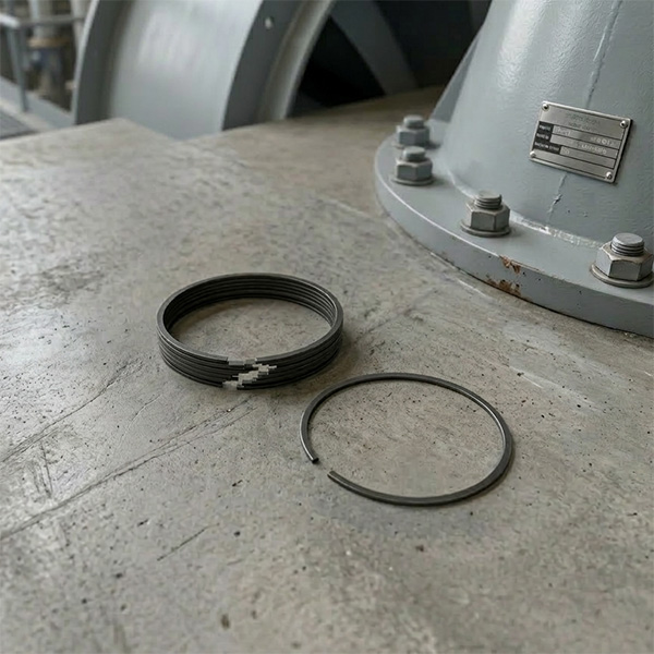
2. Auxiliary Seals: The Backup Role of O-Rings and Water Deflectors
Beyond the mechanical seal, auxiliary components plug up any other potential leakage paths. The most important are the O-rings and the water deflector ring.
O-rings are fitted at the contact points between the rotating ring and the shaft, and the stationary ring and the casing. Their material must be compatible with the pump media—boiler feed water is hot and pressurized, so you must use temperature- and oil-resistant Viton/FKM O-rings, not standard rubber, which quickly ages and cracks. Don't force them on; apply a thin layer of silicone grease for lubrication to prevent scratching by sharp shaft edges.
The water deflector ring sits outside the mechanical seal. Its job is to block external cooling water or contaminants from entering the seal chamber. If the deflector is worn or distorted, cooling water seeps into the chamber, diluting the lubricant and accelerating wear on the sealing faces. During inspection, check the deflector's sealing surface. If it has burrs, smooth them with a file; if it's deformed, replace it immediately.
3. The Seal Chamber: Creating a "Stable Environment" for Components
Seal components hate dirt and running dry. The flush water supply to the seal chamber must be clear. Booster pumps typically use a flushing line to feed low-pressure water to the sealing face, removing heat and contaminants. This flush water pressure must be slightly higher than the pump internal media pressure to prevent backflow into the chamber.
If the flush line is clogged, the sealing face temperature will spike. O-rings soften quickly, and the rings themselves can warp from overheating. During daily rounds, touch the seal chamber—it should feel cool or mildly warm. If it's hot, immediately check if the flush water pipe is blocked or if the valve is fully open.
II. Wobble-Free Fit: Assuring Shaft and Associated Component Accuracy
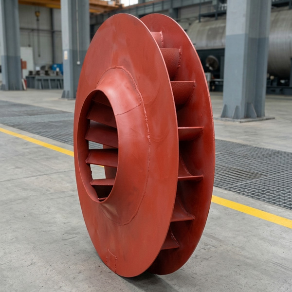
A shaft leak is often not due to a failed seal component, but a problem with the fit between the shaft, impeller, and bearings—the shaft wobbles too much, grinding the seal components down. For the HZB253-640-01-01 shaft, fitting accuracy focuses on the impeller and bearing areas.
1. Impeller Fit: Interference Control is Key
The impeller slides onto the pump shaft and transmits torque via a key. If the fit is too loose, the impeller "slips" on the journal, causing wear. If it’s too tight, forcing it on can bend the shaft, leading to excessive radial runout when rotating.
This is a "transition fit." Installation shouldn't require heating or cooling—a copper hammer should tap it into place gently, and removal requires a special tool. During inspection, measure the journal diameter and the impeller bore diameter to confirm the interference fit is within specification. If the journal is worn down, making the fit loose, the journal must be repaired, perhaps by welding and machining back to the standard size. Never compromise.
Some plants try to cut corners by spot-welding a loose impeller. The result is uneven forces on the shaft during rotation, accelerating wear elsewhere. If you face this, ditch the makeshift fixes. Contact us to repair the shaft journal and restore its correct fitting precision.
2. Bearing Fit: Clearance Determines Stability
The pump shaft is supported by bearings, and the fit clearance between the inner ring and the shaft must be precise. Too much clearance, and the shaft "shakes its head" when rotating, making the impeller and seal components wobble too. Too little, and the bearing overheats severely, potentially "welding" itself to the shaft journal.
Before installing the bearing, use a micrometer to measure the journal diameter and an internal dial gauge to measure the bearing inner ring diameter, then calculate the actual clearance. For general use, a clearance of 0.02mm to 0.05mm at room temperature is suitable, but this needs adjustment based on the pump speed and media temperature. Once installed, the shaft should turn smoothly without jamming or noticeable play.
Also, pay attention to the bearing end cap tightness. If the screws are too loose, the bearing moves axially. Too tight, and the bearing is crushed, preventing rotation. Tighten the screws diagonally and evenly, and finally, use a feeler gauge to measure the gap between the end cap and the bearing outer ring, ensuring the bearing has sufficient axial float.
3. Shaft Integrity: Straightness and Finish
A perfectly fitted component is useless if the shaft itself is defective. The HZB253-640-01-01 shaft must meet its straightness specification. A bent shaft causes radial runout during rotation, which directly destroys the seal components. During inspection, place the shaft on V-blocks and use a dial indicator to measure the Total Indicator Runout (TIR); anything over 0.03mm requires straightening.
The shaft's surface finish is also crucial. Areas interfacing with seals and bearings must have low roughness, free of scratches, burrs, or corrosion pits. These defects act like "knives," wearing out O-rings and bearing inner rings, and allowing media to accumulate, accelerating leakage. Minor scratches can be smoothed with fine sandpaper dipped in oil; deep scratches require machining.
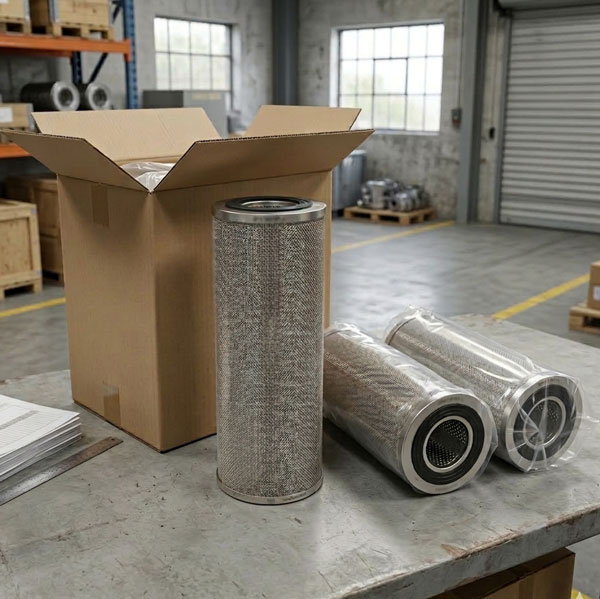
III. Inspection Checklist: Synchronized Check of Wear Parts
The shaft's sealing and fit depend on the proper function of surrounding parts. When inspecting, you can't just focus on the shaft; these wear parts must be checked simultaneously and replaced if necessary, or your shaft repair effort will be wasted.
| Wear Part Name | Inspection Focus |
|---|---|
| Steam Pump Booster Impeller Wear Ring | Check for wear on the inner bore; verify clearance with the impeller (excessive clearance leads to media recirculation, lowering pump efficiency). |
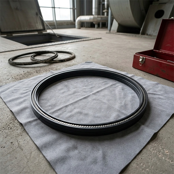
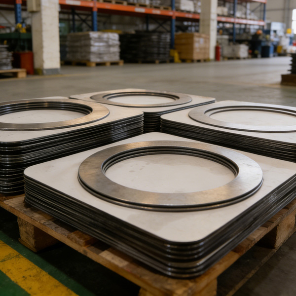
| Stainless Steel Spiral Wound Gasket | Check for damage or deformation on the sealing face; look for loose winding layers. |
| Pump Casing | Check the inner wall of the seal chamber for smoothness, corrosion, or erosion marks. |
| Wear Ring | Measure the thickness; replacement is mandatory if wear exceeds 1/3 or if cracks appear. |
| Gasket (HZB253-640-02-07) | Check for aging, hardening, or damage/impressions on the sealing face. |
| Gasket (HZB253-640-03-07) | Confirm the model matches before installation to avoid using the wrong part, which leads to poor sealing. |
For example, if the impeller wear ring is worn, media recirculates through the gap, dropping pump discharge pressure and disrupting the forces on the shaft, indirectly affecting the seal. If the spiral-wound gasket fails, the pump casing and end cover will leak—not a shaft leak, but still a performance issue. Don't wait for these parts to fail completely; address signs of wear promptly to prevent further issues.
IV. Routine Maintenance: Simple Actions, Extended Seal Life
Beyond major overhauls, daily rounds and maintenance extend the shaft's leak-free life. These simple actions catch problems early.
During every patrol, focus on three things: seal chamber temperature (below 60°C is normal), shaft vibration (no noticeable shaking by hand), and signs of leakage. If you spot minor leakage, don't stop the unit immediately. Note it down and track the leak rate—if it gradually increases, the seal components are wearing out, and a planned change is needed. If it suddenly increases, the seal has likely failed, and emergency action is required.
Regularly lubricate the bearings, using the correct grease type—do not mix. Too much or too little grease is bad: too much causes overheating, and too little causes dry friction, both of which compromise shaft stability. After greasing, run the pump for 10 minutes to ensure even lubricant distribution.
If you are unsure how to set up your patrol schedule or want to learn hands-on shaft sealing techniques, contact us for a customized maintenance checklist, making every inspection targeted and effective.
Conclusion: Pump Shaft Leak? Stop Wasting Money, Find the Real Fix
The sealing and fit of the HZB253-640-01-01 pump shaft boil down to one word: "Precision." The seal must fit precisely, the shaft and associated parts must fit precisely, and daily maintenance must be meticulous. Many plant shaft leaks are not due to poor part quality but to incorrect installation, improperly set fits, or failure to replace all associated wear parts simultaneously.
If your plant's booster pump shaft consistently leaks, or if leaks re-occur frequently after maintenance, stop the costly cycle of repeatedly replacing only the seal components. Contact us. Our technical team can troubleshoot on-site, providing end-to-end solutions—from shaft precision detection and fit clearance adjustments, to seal selection and matching—to eliminate leakage, ensure stable operation of your booster pump, and minimize non-scheduled downtime losses.
HKCYT-2025-11-13


-
Looking at Abnormal Wear on U250-Y01 Induced Draft Fan Moving Blades
Understand why U250-Y01 induced draft fan blades wear out and how to maintain mechanical linkages. We provide U250-Y01 blades, seals, and connecting rods.03-23
-
Easy Maintenance with the SDGLQ-60T-36K Duplex Oil Filter for Coal Mills
Learn how to switch the SDGLQ-60T-36K duplex filter element without stopping your coal mill. No oil flow interruption, stable pressure, and zero bypass. Get a quote today.03-17
-
Keeping Your ID Fan Safe with the U2616G2106Y01 Blade Seal Ring
Protect your HU25042-221G fan with the U2616G2106Y01 blade seal ring. Learn how multi-stage sealing prevents bearing jams, blade sticking, and fan stalls.03-12
-
Stopping Oil Leaks with the UYG35/20G010 ID Fan Seal Ring
Stop bearing box leaks with the UYG35/20G010 ID fan seal ring. Learn how gap control and thermal expansion prevent grip failure in induced draft fan spare parts.03-11
-
How to Detect Micro Leakage in Feed Water Pump Gasket FA1D56-03-09 Before It Causes Shutdown
Learn the common failure modes of feed water pump cooling water jacket sealing gasket FA1D56-03-09, including aging, creep relaxation, and mechanical damage. Understand external signs, micro leakage detection methods, and practical maintenance tips to prevent pump shutdown and reduce repair cost.03-02


