


Analysis of Failure Modes and Monitoring Techniques for FA1D56-01-03A Pump Shafts
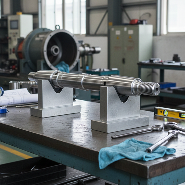
The FA1D56-01-03A pump shaft is the main power transmitter for feed pumps in thermal power plants. It spins at high speeds to drive impellers while dealing with constant alternating stress. Thermal shocks are also a daily reality—quick temperature swings during startups and stops cause internal stress points. All these factors make the pump shaft a high-risk part for failure. Learning how it fails and how to spot damage without taking the pump apart is the only way to avoid a disaster. If a pump shaft snaps unexpectedly, it usually means a forced shutdown and a massive financial loss.
1. Main Failure Modes: Why Damage Happens
Fatigue cracking is the #1 killer of the FA1D56-01-03A pump shaft. Constant stress cycles start tiny cracks at surface flaws. Over time, these cracks grow until the shaft eventually snaps.
Stress tends to pile up at sharp spots like shaft shoulders and keyways. High-speed operation makes even a tiny scratch turn into a deep crack very quickly. Our original FA1D56-01-03A pump shaft is specially reinforced at these high-stress zones to lower the risk.
Thermal cracking is another big threat. Fast heating or cooling creates thermal stress that adds to the mechanical load. If it goes past the material's limit, micro-cracks appear on the surface and dig inward. You also have to watch for wear—friction at the journals or corrosion from the water can ruin the shaft's dimensions and fit.
2. Non-Dismantling Monitoring: Early Warning Signs
Vibration monitoring is the best way to check the FA1D56-01-03A pump shaft while it's still running. When a crack starts forming, the vibration signal changes. You need to watch the amplitude and frequency patterns closely.
If you see a sudden jump in a specific frequency along with a rhythmic throb, a crack might be growing. Spectrum analysis can help pin down where the damage is. We offer calibration services for monitoring the FA1D56-01-03A pump shaft to make these predictions more accurate.
Ultrasonic testing (UT) is another great tool. It sees through the metal to find internal cracks. You just press the probe against the shaft surface during a short outage. There’s no need to pull the whole rotor out.
3. Support Monitoring: Catching Abnormal Parameters
Temperature checks help confirm the shaft's health. If the journal area gets too hot, it could be a sign of heavy wear or a crack causing extra friction. Combined with vibration data, this makes your diagnosis much stronger.
Oil analysis also helps. As the FA1D56-01-03A pump shaft wears or cracks, tiny metal flakes fall into the lube oil. If your lab report shows a sudden spike in iron (Fe) levels, you likely have fatigue damage starting. Even your ears can help—a cracked shaft often makes an irregular clicking or humming noise.
4. Best Practices: Reducing the Risk of Failure
To keep the FA1D56-01-03A pump shaft alive longer, you have to control how the pump runs. Avoid too many starts and stops to limit thermal shock. When you do start up, follow the temperature ramp-up rules strictly. Keep your bearings and seals in top shape. If a bearing sticks, it puts uneven force on the shaft, creating a localized stress point.
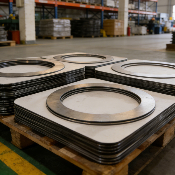
The stability of the FA1D56-01-03A pump shaft also depends on the parts around it. Below is a list of core parts that must fit perfectly to keep the shaft safe:
| Part Name | Model / Specification |
|---|---|
| Mechanical Seal | HZB253-H75/110-G115-E1 |
| Spring Plate | HTHP-01-02-19-08 |
| Gasket | ZB253-640-03-06 |
| Booster Pump Mech Seal | FAID56 |
| Guide Vane | DG600-240-04-13 |
| Shaft Sleeve | FAID56-01-05 |
| 1st Stage Impeller | FT9Q36M-03-02 |
| Seal Retaining Ring | DG600-240-07-02 |
| Thrust Bearing Assembly | HZB253-640A-02-05-00 |
| Gasket | FA1D56-02-04 |
| Guide Vane (Mid-Stage) | 0FK5F32KM-04-04 |
5. Dealing with Damage: Act Fast
If you find a crack in the FA1D56-01-03A pump shaft, you have to deal with it immediately. Very light surface cracks can sometimes be ground out and repaired, but you must do stress-relief treatment afterward.
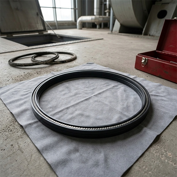
If the crack is deep or in a critical spot, don't risk a repair—just replace the shaft. Using a patched-up shaft is a ticking time bomb. When you replace it, always use an original FA1D56-01-03A pump shaft to ensure the metal and precision are correct.
Conclusion: Monitoring Keeps the Unit Running
Failures in the FA1D56-01-03A pump shaft usually come from a mix of fatigue and heat. By using vibration and ultrasonic tools, you can catch the early signals and avoid a catastrophic break.
Need an original FA1D56-01-03A pump shaft, technical monitoring, or on-site testing? Contact us. We provide the high-quality shafts and the expert support to keep your feed pump running safely.
HKCYT-2026-01-21


-
Looking at Abnormal Wear on U250-Y01 Induced Draft Fan Moving Blades
Understand why U250-Y01 induced draft fan blades wear out and how to maintain mechanical linkages. We provide U250-Y01 blades, seals, and connecting rods.03-23
-
Easy Maintenance with the SDGLQ-60T-36K Duplex Oil Filter for Coal Mills
Learn how to switch the SDGLQ-60T-36K duplex filter element without stopping your coal mill. No oil flow interruption, stable pressure, and zero bypass. Get a quote today.03-17
-
Keeping Your ID Fan Safe with the U2616G2106Y01 Blade Seal Ring
Protect your HU25042-221G fan with the U2616G2106Y01 blade seal ring. Learn how multi-stage sealing prevents bearing jams, blade sticking, and fan stalls.03-12
-
Stopping Oil Leaks with the UYG35/20G010 ID Fan Seal Ring
Stop bearing box leaks with the UYG35/20G010 ID fan seal ring. Learn how gap control and thermal expansion prevent grip failure in induced draft fan spare parts.03-11
-
How to Detect Micro Leakage in Feed Water Pump Gasket FA1D56-03-09 Before It Causes Shutdown
Learn the common failure modes of feed water pump cooling water jacket sealing gasket FA1D56-03-09, including aging, creep relaxation, and mechanical damage. Understand external signs, micro leakage detection methods, and practical maintenance tips to prevent pump shutdown and reduce repair cost.03-02


